EasyManua.ls Logo

Xtralis VESDA-E VEP-A10-P User Manual

Xtralis VESDA-E VEP-A10-P
114 pages
To Next Page IconTo Next Page
Page #1 background imageLoading...
Page #1 background image
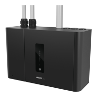
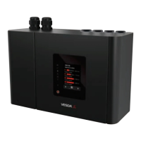
VESDA-E VEP-A10-P
Product Guide
VEP-A10-P (4 Pipes)
April 2016
Document: 22071_11
Part Number: 30311

Table of Contents

Question and Answer IconNeed help?

Do you have a question about the Xtralis VESDA-E VEP-A10-P and is the answer not in the manual?

Xtralis VESDA-E VEP-A10-P Specifications

General IconGeneral
BrandXtralis
ModelVESDA-E VEP-A10-P
CategorySmoke Alarm
LanguageEnglish

Summary

General Warning

Document Scope and Conventions

Scope

Defines the purpose and intended audience of the product guide.

Document Conventions

Explains typographic conventions and icons used throughout the document.

Contact Information

Regulatory Compliance and Standards

Codes and Standards for Air Sampling Smoke Detection

Details relevant codes and standards for smoke detection and electrical connections.

Regional Regulatory Requirements

UL and ULC Requirements

Specifies requirements for UL and ULC compliance in installations.

European Installations and EN 54-20

Outlines requirements for European installations and EN 54-20 standards.

Introduction to the VEP-A10-P

Key Product Features

Lists the advanced features and capabilities of the VEP-A10-P detector.

Product Information

Detector Components and Operation

Identifies components and explains the functional principle of the VEP-A10-P detector.

Front Panel Interface and Controls

Status LEDs and Reset/Disable Button

Details the function of front panel LEDs and the reset/disable button.

Touchscreen Interface Details

Main and Airflow Screen Information

Describes the main screen and airflow screen displays on the detector.

Internal Buttons and Other Screens

AutoConfig Button Operations

Describes how to use the AutoConfig button for normalization and auto-learning.

Communication Ports and VESDAnet

Communication Ports Overview

Details the USB, Ethernet, and WiFi ports for detector communication.

VESDAnet Connectivity

Explains the VESDAnet network communication capabilities.

Detector Specifications

Detector Dimensions

Pipe Network Design and Installation

Pipe Network Design Considerations

Key points to consider when designing the air sampling pipe network.

Sampling Pipe Installation Considerations

Important factors for correctly installing the sampling pipe network.

Managing Exhaust Airflow

Installation Procedures

Preparing the Detector for Installation

Steps for initial preparation of the VEP-A10-P detector before mounting.

Detector Mounting Guidelines

General Mounting Requirements

Ensures correct mounting orientation and clearance for the detector.

Inverting the Detector for Installation

Procedure for inverting the detector's orientation for specific installation needs.

Detector Mounting Methods

Mounting with Mounting Bracket

Detailed steps for mounting the detector using the provided mounting bracket.

Mounting Using the Mounting Template

Instructions for installing the detector using the wall mounting template.

Wiring and Cabling

General Wiring and Cabling Inlets

Information on wire sizes and cable entry points for detector wiring.

Electrical Connections and Power

Socket Locations and Power Source Connection

Details on detector sockets and connecting the 24 VDC power supply.

Communication and Networking

Connecting Multiple Detectors and Network Options

Covers daisy-chaining power, communication ports, and VESDAnet connection.

Relay Configurations and Assignments

Relay Functionality and Default Assignments

Details on detector relays, their operation, and default functional assignments.

General Purpose Input (GPI) Configuration

GPI Functionality and Wiring

Describes GPI options, including unmonitored, monitored, and PSU monitoring.

Wiring to External Systems

Wiring to FACP and Addressable Loop Module

Illustrates correct wiring for connecting to FACP and addressable loop modules.

Backup Battery Calculation

Powering Up the Detector

Installation Checklist and Verification

Preliminary System Check

Detector Configuration

Establishing Communication with Xtralis VSC

Steps required to set up communication between VSC software and the detector.

Defining Connection Profiles

How to create and manage connection profiles for various communication methods.

Connecting to the Detector

Connecting via USB, Ethernet, or WiFi

Procedures for connecting the detector via USB, Ethernet, or WiFi.

Connecting via VESDAnet

Security and Access Control

Authentication and Access Levels

Details on password authentication, user levels, and PIN management for secure access.

Detector Commands Overview

Configuration Options in Xtralis VSC

General and VESDAnet Options

Basic identification settings and VESDAnet communication configuration.

Ethernet Configuration Settings

WiFi Configuration Settings

Smoke Threshold Configuration

Airflow and Filter Configuration

Airflow Options and Thresholds

Settings for normal airflow behavior, pipe usage, and aspirator speed.

Filter Service Interval Configuration

Defines the time period after which a filter fault will be generated.

Referencing Configuration Options

General Purpose Input (GPI) Options

Relay Assignment and Configuration

Button Lockout Options

Factory Default Settings Reference

Commissioning Procedures

AutoLearn Smoke Process

Procedure for the detector to learn environment and set smoke thresholds.

Automated Learning and Testing

AutoLearn Flow Process

Procedure for the detector to learn and set airflow thresholds.

Commissioning Smoke Test

Procedure for testing pipe network integrity and smoke transport time.

Routine Maintenance Schedule

Standby Mode for Maintenance

How to put the detector into standby mode to safely perform maintenance.

Opening the Detector Door

Replacing the Detector Filter

Removing the Detector Fascia

Replacing the Aspirator Module

Replacing the Smoke Detection Chamber

Replacing the Sampling Module

Detector Spare Parts List

Troubleshooting Guide

Fault Reporting and Front Panel Troubleshooting

How faults are reported and how to diagnose issues using the front panel display.

Troubleshooting with Xtralis VSC Software

Commissioning Forms and Documentation

Commissioning Forms and Data Recording

Forms and instructions for recording commissioning details and test results.

Glossary of Terms

Related product manuals