VESDA-EVEP-A10-P Product Guide
38 www.xtralis.com
Notes:
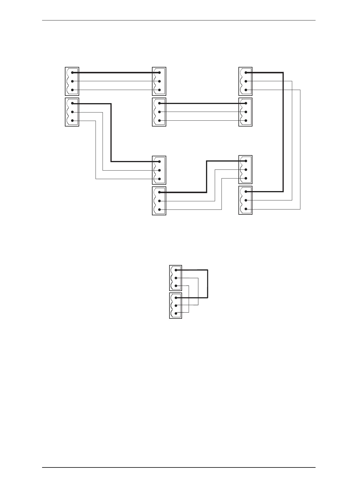
l The polarity of the data wires must be maintained throughout the network.
l In order for the detector to be able to detect ground faults on the VESDAnet wiring, the Ground Reference
Terminal (Figure4-33) must be connected to the local ground.
A+
A-
B-
Shield
Module 1 Module 2 Module 3
Module 5 Module 4
Shield
B+
A+
A-
B-
Shield
Shield
B+
A+
A-
B-
Shield
Shield
B+
A+
A-
B-
Shield
Shield
B+
A+
A-
B-
Shield
Shield
B+
(VESDA-E VEP)
Figure4-35: Example closed loop VESDAnet network
The VESDA-E VEP-A10-P detector is shipped with the VESDAnet A and B terminals looped. Remove the A
and B links prior to connecting the detector to the VESDAnet. If the detector is not to be networked with other
devices, then do not remove the A and B links.
Figure4-36: Closed loop for standalone detectors with VESDAnet capability
Note: Refer to the VESDA-E Communications Guide for further information.