VESDA-EVEP-A10-P Product Guide
36 www.xtralis.com
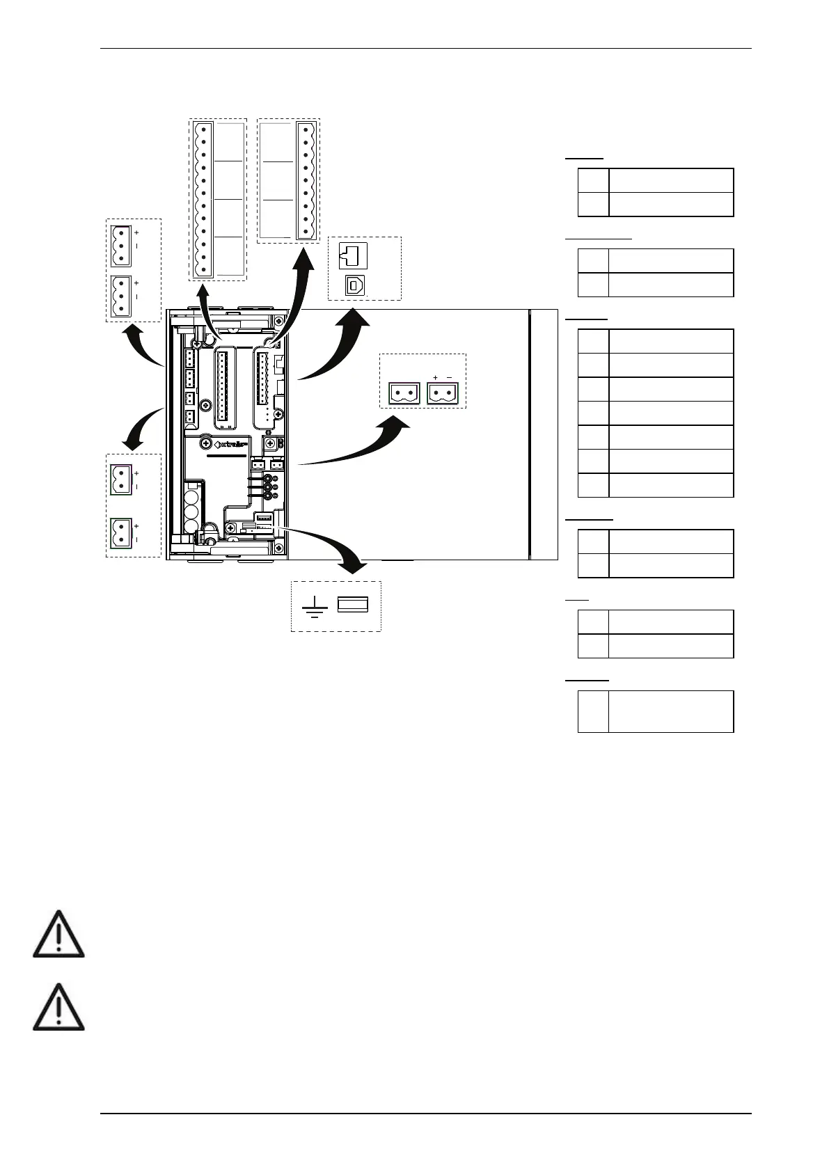
4.3.2 Socket Locations
SH
SH
NC C NO NC C NO
NC C NO
2 [MINOR F]
NC C NO
1 [ISOL]
5 [ACTION]
NO C NC
6 - FIRE 1
NO C NC
7 [FIRE 2]
NO C NC
A
B
C
D
H
G
F
E
I
J
K
L
M
O
N
4 [ALERT]
3 - URGENT F
P
Legend
Power
A Power Out
B Power In
VESDAnet
C VESDAnet B
D VESDAnet A
Relays
E 1 - Disable (Isolate)
F 2 - Minor Fault
G 3 - Urgent Fault
H 4 - Alert
I 5 - Action
J 6 - Fire 1
K 7 - Fire 2
Comms
L USB
M Ethernet
GPI
N Monitored GPI
O Unmonitored GPI
Ground
P Ground Reference
Terminal
Figure4-33: Socket Locations
4.3.3 Power Source
There are two sets of power terminals on the main board (Figure4-33). Connect a 24 VDC power supply which
is compliant with local fire protection codes and standards to the PWRINsocket, and if required loop out to
another detector via the PWROUT socket.
The detector will not operate if the power supply polarity is reversed.
Caution: Operating the detector when DC supply voltage is outside the specified voltage range may
cause damage to internal components. For further information refer to the Product
Specifications on page 11.
Attention : Le détecteur de fonctionnement lorsque la tension d'alimentation DC est en dehors de la plage
de tension spécifiée peut endommager les composants internes. Pour plus d'informations, se
reporter au notice descriptive du produit à la page 11.