VESDA-EVEP-A10-P Product Guide
www.xtralis.com 37
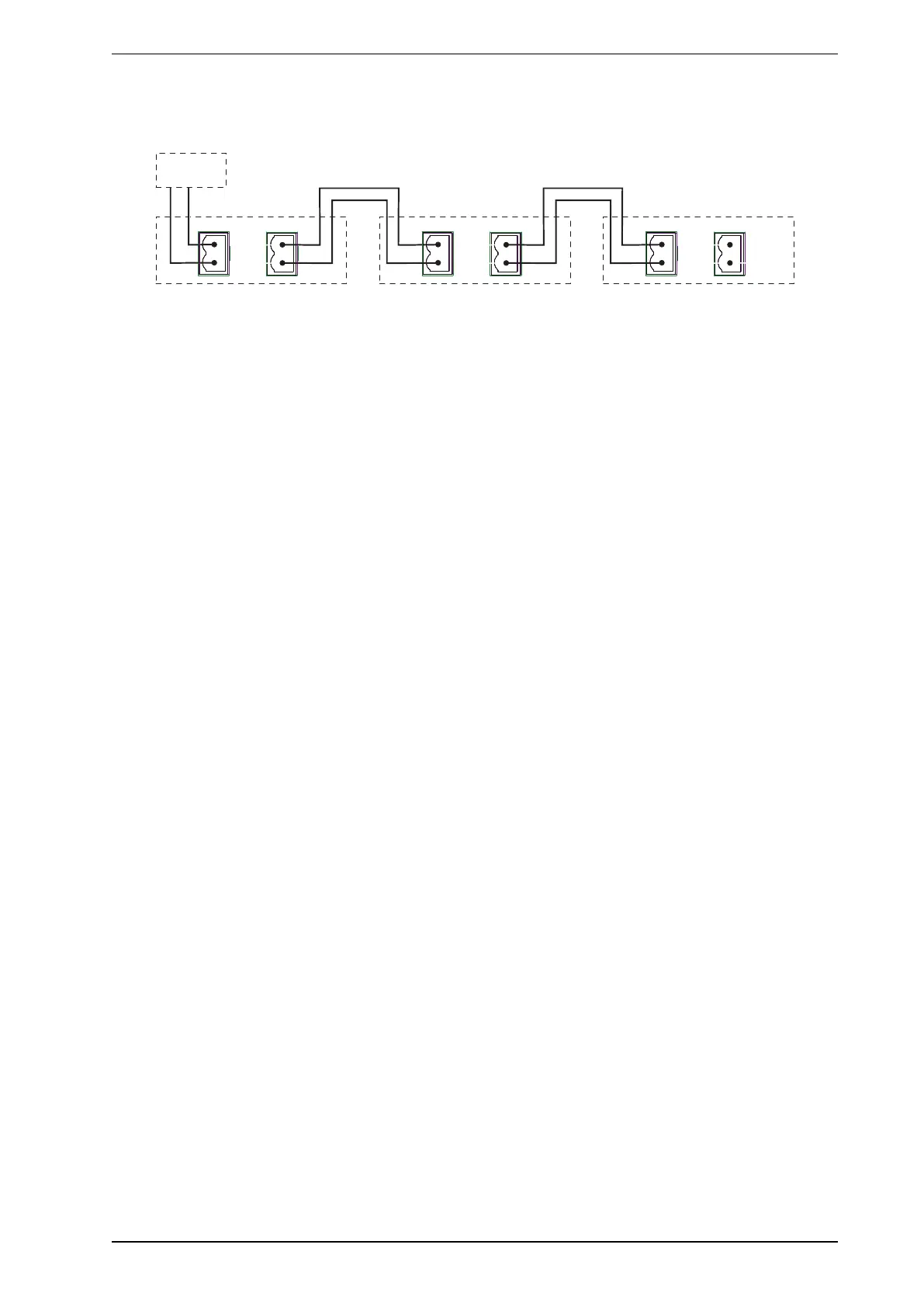
Power to Multiple Detectors
Up to three VESDA-EVEP or VEU detectors may be daisy chained to the same power supply by connecting
the PWROUTpower passthrough socket to the PWRINsocket on each subsequent detector.
Detector 1 Detector 2 Detector 3
PWR IN
PWR
OUT
+
+
_
_
PWR IN
PWR
OUT
+
+
_
_
PWR IN
PWR
OUT
+
+
_
_
PSU
Figure4-34: Multiple Detectors powered by a single power supply
Compliance
It is recommended that the power supply be compliant with local codes and standards required by the regional
authority. For code-specific information, refer to Codes and Standards Information for Air Sampling Smoke
Detection on page iii.
4.3.4 Communication Ports
The front door must be opened in order to access the communication ports. Refer to Section 7.2 for
information on opening the front door and Figure4-33 for the physical location of the ports.
Note: For all connection methods the detector also provides a gateway to all the other devices on the
VESDAnet network.
USB
The USB port is used for initial configuration and local maintenance or servicing of the VEP-A10-P using a PC
installed with Xtralis VSC software.
Install Xtralis VSC prior to connecting the VEP-A10-Pto the PCor Laptop. This ensures that the required
USBdrivers are present.
Notes:
l The USB port must not be used for permanent field connection. For example, do not use a USB to
Ethernet or USB to Wifi adaptor to connect the detector to a LAN using USB.
l Refer to the Xtralis VSC documentation for operating system compatibility information.
Ethernet
The Ethernet port is used for permanent network connection to the VEP-A10-P. An Ethernet lead can be
routed through the cable entry ports and plugged into the Ethernet port.
Use a standard Ethernet lead when connecting the VEP-A10-P to a network switch, router or directly to a
PCor laptop.
WiFi
The WiFi module provides wireless connection of the detector to the building network for the purpose of
configuration and secondary monitoring.
4.3.5 VESDAnet
VESDAnet is a bidirectional data communication network between connected VESDA-E devices. VESDAnet
connectivity is available on the VEP-A10-P detector. Refer to Section 2.6 for further information.
It is recommended that RS 485 (Belden 9841 - 120 Ohm) twisted pair cables be used for including the devices
in the network.
The network cables are terminated at the VESDAnet A and B Terminals. Cabling from one VESDA-E device
is brought into the detector at one terminal and looped out to another device on VESDAnet from the other
terminal.