VESDA-EVEP-A10-P Product Guide
www.xtralis.com 29
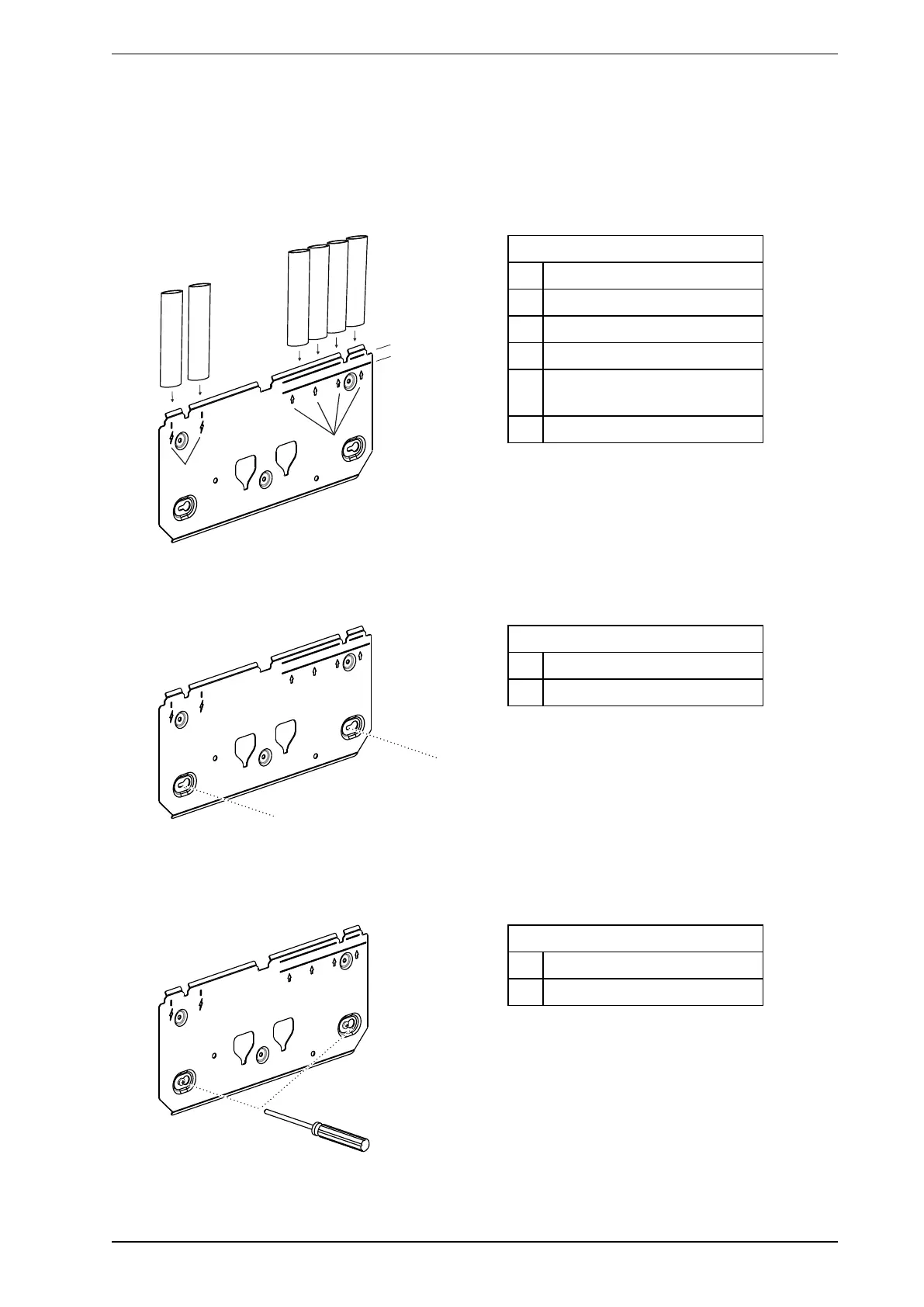
4.2.2 Mounting the Detector with the Mounting Bracket
1. Position the mounting bracket (A) to allow sampling pipes (B) and electrical conduit (C) to line up
horizontally with the alignment marks (D) and vertically with the appropriate pipe depth line (Figure4-17).
l 3/4 inch IPS pipe (1.05 inch OD) should vertically align with the top depth line (E).
l 25mm pipe should vertically align with the bottom depth line (F).
Legend
A Mounting bracket
B Sampling Pipes
C Electrical Conduit
D Pipe alignment marks
E 3/4 inch IPS pipe (1.05 inch
OD) depth
F 25 mm pipe depth
Figure4-17: Position Mounting Bracket in line with pipes
2. Mark the mounting surface through two keyholes (B) on the mounting surface (Figure4-18).
Legend
A Mounting bracket
B Keyholes
Figure4-18: Mark keyholes
3. Insert two screws into the mounting surface at marked positions (Figure4-19).
4. Slide plate onto the mounting screws and tighten them with a screwdriver (B).
Legend
A Mounting bracket
B Screwdriver
Figure4-19: Tighten screws