VESDA-EVEP-A10-P Product Guide
www.xtralis.com 43
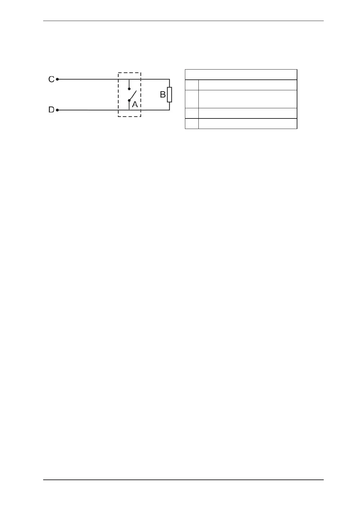
4.3.11 Typical Wiring for Monitored GPI for PSU Monitoring
The diagram below shows the correct way to configure power supply monitoring. It also shows where an End
Of Line (EOL) resistor is correctly installed. Refer to Section 4.3.8 on page 41 for further information.
Legend
A External device (1 to N)
B End of Line Resistor at device end of
wiring
C GPI Pin 1
D GPI Pin 2
Figure4-39: Power Supply Connection Diagram