VESDA-EVEP-A10-P Product Guide
42 www.xtralis.com
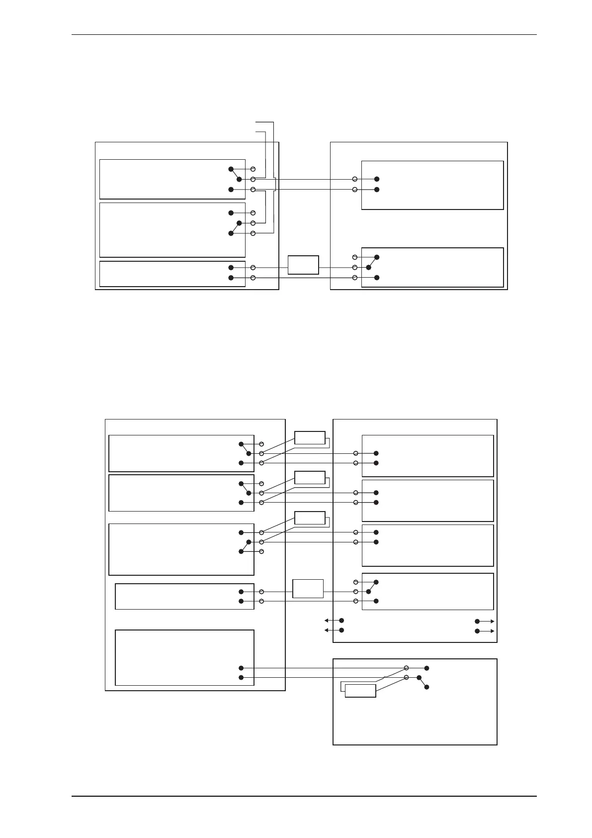
4.3.9 Typical Wiring to Fire Alarm Control Panel (FACP)
The diagram below shows the correct way to wire VESDA-E detectors to a conventional fire alarm control
panel (FACP).
Normally Closed (NC)
CommonFIRE 1 (C)
(NO)Normally Open
Normally Closed (NC)
Common (C)URGENT FAULT
(NO)Normally Open
Unmonitored GPI
( “R ”)Set to eset
Dete torc
(NC)
(C)
(NO)
Input
EOL = Normal
Short = Fire
Open = Fault
To next detector
or End of Line resistor (EOL)
Fire Panel (FACP)
+
-
+
-
5-30VDC
The relay is
energised on reset.
Relay shown energized which
is the no-fault condition
Figure4-37: Typical wiring to a fire panel with EOL
4.3.10 Typical Wiring to Addressable Loop Module
This wiring example is for wiring VESDA-E detectors to a typical third party Input/Output Loop module 3
inputs 1 output.
Note: These are example drawings. Refer to the appropriate product manual for the exact wiring details of
the third party equipment.
Normally Closed (NC)
Common (C)Fire 1
Normally Open (NO)
Normally Closed (NC)
CommonAction (C)
Normally Open (NO)
Normally Closed (NC)
Common (C)Fault
Normally Open (NO)
Fire Input
EOL* = Normal
Short = Fire
Open = Wiring Fault
Pre Alarm
EOL* = Normal
Short = Fire
Open = Wiring Fault
Fault Input
EOL* = Normal
Short = Detector Fault
Open = Wiring Fault
EOL*
EOL*
EOL*
(NC)
(C)
(NO)
Monitored GPI
( “Mains OK”)Set to
PSU
+
-
+
-
5-30VDC
(NC)
(C)
(NO)
This shows normal operation (no fault).
EOL*
The relay is
energised
on reset.
The power supply’s fault reporting
relay is energized.
Relay shown energized which
is the no-fault condition
EOL* = Normal
PSUShort = Fault
Open = Wiring Fault
3 Inputs 1 Output Loop Module
*EOL: End of Line Resistor
To next detector
To FACP
Unmonitored GPI
(Set to “Reset”)
Detector
Figure4-38: Input/Output Loop Module with EOL