Do you have a question about the Xtralis VESDA VLC and is the answer not in the manual?
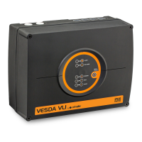
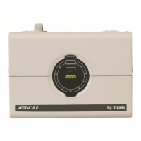
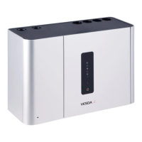
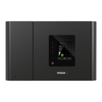
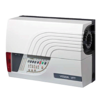
Describes the available VLC detector models and their purposes.
Lists the key features and capabilities of the VLC detector.
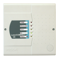
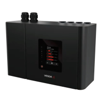
Explains the LEDs and Reset/Isolate button on the detector's front panel.
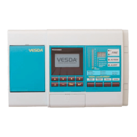
Details the components and functions of the optional remote display module.
Describes the LCD Programmer for configuration and maintenance.
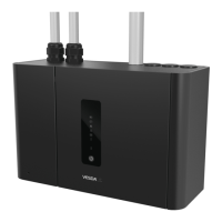
Illustrates the front view and internal components of the VLC detector.
Provides detailed technical specifications for the VLC detector.
Shows the physical dimensions of the VLC detector with diagrams.
Lists the default configuration settings for various detector parameters.
Instructions on how to secure the detector's mounting bracket.
Step-by-step guide for physically installing the VLC detector.
Details on connecting the detector to the air sampling pipe network.
Information on connecting the air exhaust pipe from the detector.
Explains the function and layout of the termination card.
Wiring details for connecting the detector to VESDAnet.
Wiring information for the detector's relay outputs.
Details on connecting programming devices to the detector.
Wiring instructions for auxiliary and GPI terminals.
Diagrams showing typical wiring to a fire alarm control panel.
Example wiring for connecting to an addressable loop module.
A checklist to ensure all installation steps are completed correctly.
Instructions for safely opening and closing the detector enclosure.
Steps for removing and replacing the detector's aspirator unit.
Details of the internal cable loom interconnecting components.
| Type | Aspirating Smoke Detector |
|---|---|
| Power Supply | 24 V DC |
| Communication | RS-485, Ethernet |
| Humidity Range | 10% to 95% RH (non-condensing) |
| IP Rating | IP30 |
| Detection Technology | Laser |
| Sensitivity Range | 0.005% obs/m to 20% obs/m |
| Air Sampling Type | Continuous |
| Aspiration | Via pipe network |
| Pipe Length | Up to 100 m |
| Number of Sampling Points | Up to 20 |
| Alarm Levels | Alert, Action, Fire |
| Operating Voltage | 18 – 30 VDC |
| Communication Interface | Relay |
| Operating Temperature | 0 to 50 °C |
