VESDA by Xtralis VESDA VLC Product Guide
www.xtralis.com 19
4.4 Relay settings and conditions to change states
Relay # Relay Condition for relay to change state
1 Fault This relay is de-energized when one of the following
conditions occur:
l Fault found on detector or on VESDAnet loop
l Air flow normalization is initiated
l System isolation is initiated
When the Overlay Alert function has been selected,
this relay is deenergized once the Alert Threshold is
initiated
2 Pre-Alarm This relay is energized once the Pre-Alarm
threshold is initiated
3 Fire This relay is energized once Fire Alarm threshold is
initiated
Table 4-3: Default relay settings and conditions to change state
4.5 Auxiliary / GPI Terminals
The Bias, Reset (GPI) and LED terminals are located on the termination card (refer to Figure 7-1 on
page 25 and Figure 7-2 on page 25). These terminals have the following functions:
l Bias Terminals: These output terminals provide 10 VDC supply to initiate the reset input
terminals via a remote reset/isolate switch.
l LED Terminals: These output terminals provide a 5 V, 15 mA DC supply via a 220 ohm
resistor to power a remote LED.
l Reset (GPI) Terminals: These terminals are also known as the General Purpose Input (GPI)
and are used for Reset, Mains OK or Standby functions. The input terminal requires a voltage
supply between 5 V and 24 VDC to operate. The voltage input to this terminal is isolated from
the system by an opto-coupler device. Connect the Reset (+) terminal to the positive output
and the Reset (-) terminal to the ground output of the external device (for an example of use
refer to 8 on page 29).
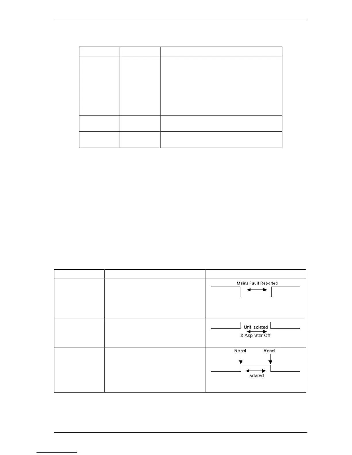
Function State Change
Mains OK The detector monitors the state of the
external power supply and responds to the
following conditions.
Mains OK ≥ 5 VDC is at this terminal
Mains Fail ≤ 2 VDC is at this terminal
Standby Mode The detector Isolates and the aspirator turns
OFF when ≥ 5 VDC is at this terminal.
Note: No Alarms can be generated in
this state
Reset Isolate While power is applied to the GPI the
detector is isolated. In addition, the
connection of power to the GPI resets the
unit.
≥ 5 VDC Detector Isolates
≤ 2 VDC Detector Reset
Table 4-4: GPI functions