Preventive Maintenance
Operation Manual69
NOTE: The boom angle indicator is a plumb arrow with
angular graduations from -5 to +70.
Figure 86. Boom Angle Indicator
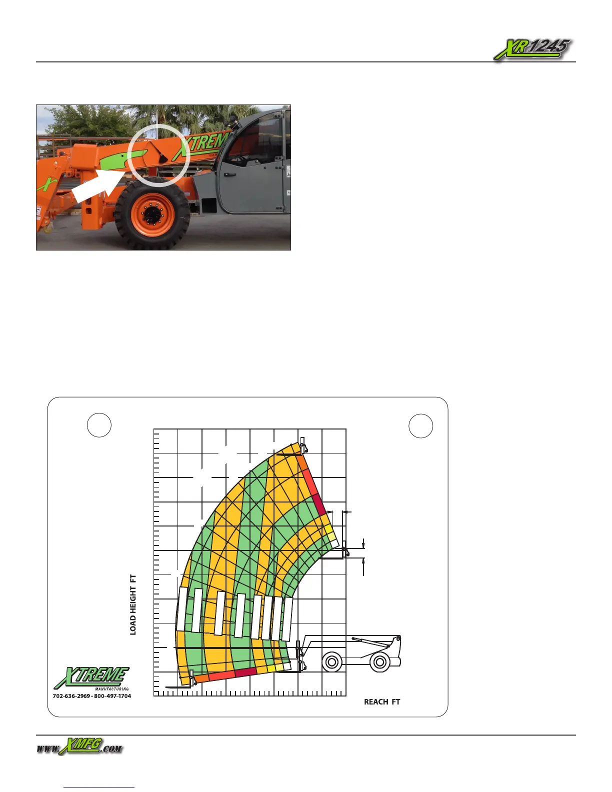
Reading Load Capacity Charts
To accurately read the load capacity charts, you must
determine three (3) things:
• Weight of the load being lifted
• Height of structure where load is to be placed
• Distance from front tires where load will be placed
For example:
1. The operator determines load weight and makes sure
load does not exceed fork, attachment, or boom capacity.
• The load is 6,614 lbs.
2. The operator safely moves the load to a loading position.
• places forks under load
• tilts and raises load safely
• fully retracts boom
• drives forklift to position perpendicular to structure
• levels the forklift
3. The operator determines height of structure where load
is to be placed.
• The structure height is 26.2 feet from ground level.
4. The operator determines distance from front tires where
load will be placed.
• The distance in front of forklift where load will be
placed is 19.6 feet.
5. Operator reads load capacity chart for attachment
carriage to learn it will be safe to place the load at any
boom angle with the boom extend letter “E” showing.
Figure 87. Load Capacity Chart
XR1045 LOAD CHART - STANDARD CARRIAGE
35
30
25
20
15
10
5
0
35
30
25
20
15
10
5
40
45
50
P/N 17020-000
0
30
25
15
10
5
40
45
35
50
0
55
60
20
65
68
BOOM ANGL E
H
G
F
E
D
B
A
C
H
F
B
E
D
C
A
G
5
9,000 LBS
8,000 LBS
6,000 LBS
4,500 LBS
3,000 LBS
1,800 LBS
2,200 LBS
2.0 FT
LOAD
CENTER
2.0 FT
LOAD
CENTER
10,000 LBS
LOAD RATINGS
SHOWN ARE FOR
VEHICLES EQUIPPED
WITH FOAM FILLED
TIRES ONLY.
5,000 LBS AT 24 IN
MIN CAPACITY FORK
(10,000 LBS PAIR).
 Loading...