Electronic Drive Manual
2
Power Supply: 1 x 115V ±10%, 50/60Hz and
1 x 208-230V ±10%, 50/60Hz
The NEC and local codes must be followed at all times.
The branch circuit supplying power to the pump must be
tted with a suitably sized circuit breaker. If a ground
fault CB is used, ensure that the CB is suitable for use
with inverter driven appliances.
2.1 Power supply connection
1. Open the terminal box cover removing the screws, g. 4.
2. Tighten the ½” NPT electrical tting into the conduit
connection of the pump.
3. Route power wiring through conduit to the terminal
block.
4. Connect the electrical conduit to the ½” NPT tting.
a. Connect the ground (earth) wire; be sure that
the ground (earth) wire is sized at least as large as
the phase wires.
b. Connect the phase wires.
5. Close the terminal box cover.
CAUTION:
If stranded wire is used to connect power to the
pump make sure that all individual strands enter the
terminal block as the wire is inserted. Peeled back
strands can cause a short circuit hazard at the pump
terminal block connections.
2.2 I/O connection
1. Open the terminal block removing the screws.
2. Connect the control wiring according to the terminal
block diagram. See Figure 6 in the appendix and
the requirements of sec. 2.3 and 2.4.
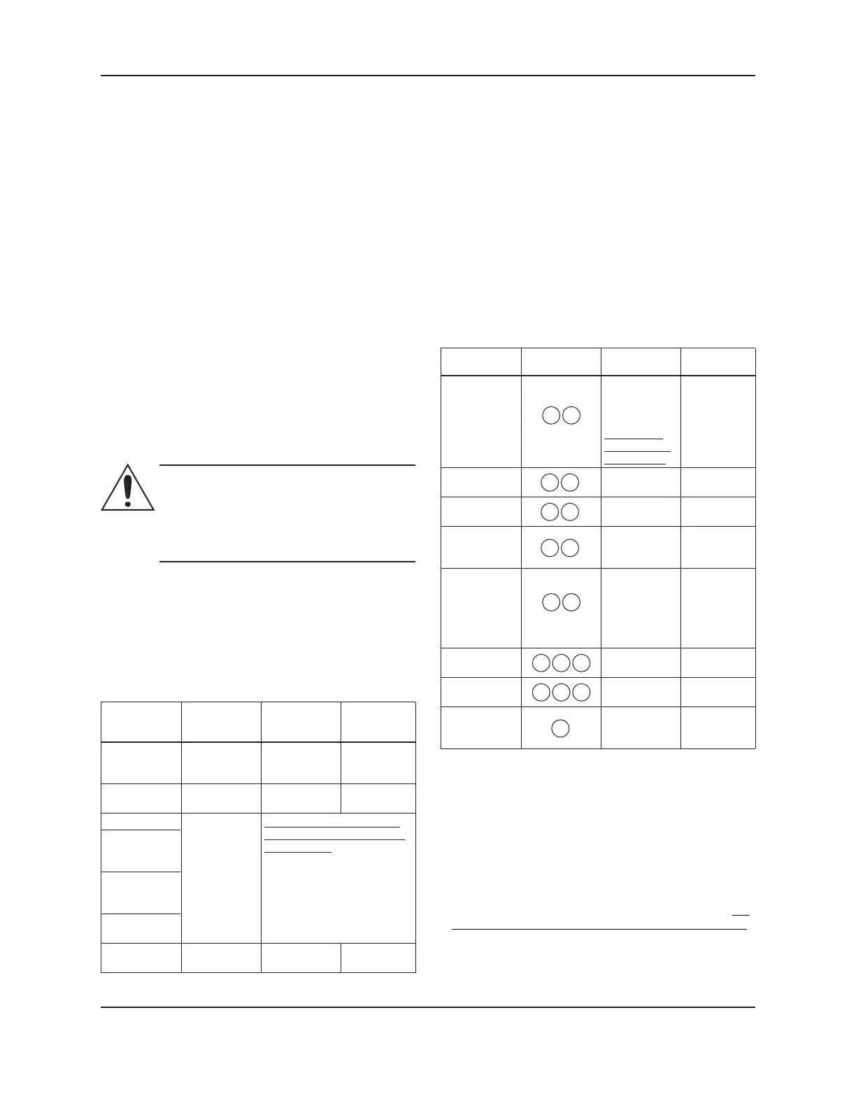
2.3 Wiring
Power and ½” NPT for M16 cable M16 cable
control signal power wiring gland (1) for gland (2) for
types control wire control wire
Power supply 3x14 AWG Min.
and ground wire size
wires
Fault relay 2x20 (AWG) 2x20 AWG
(high volt) (low volt)
Analog 0-10V
External
pressure
sensor
External
temperature
sensor
External start/
stop
Communication Bus cable
bus
Note: If power wiring is used for the fault relay
terminals, the power wiring must be routed through the
½” NPT conduit (dedicated for power wiring). However
if low voltage power is used for the fault relay control, it
must be routed through one of the M16 cable glands.
For all electrical connections use heat resistant wires or
cable rated for at least 194°F (90°C). The cables should
not touch the motor housing, the pump or the piping.
Power and control wires must be run in separate
channels.
2.4 Connection diagram
With reference to Figure 6 in the appendix:
Function Terminal Contact See section
pair rating
External 11 12 2.5.1
start/stop
External analog
7 8 2.5.2
input 0-10V
Fault signal
4 5
Max 250V at 2A 2.5.3
(inductive load)
External 15VDC sourcing 2.5.4
pressure sensor 9 10 for 2-wire
input 4-20mA DP sensor
External
temperature 13 14 2.5.5
sensor input
Communication
15 16 17 TIA/EIA RS485 2.5.6
bus (standard)
Communication
18 19 20 TIA/EIA RS485 2.5.7
bus (optional)
Optional
wireless or 21
RS485 module
2.5 I/O description
2.5.1 External start/stop [(11) (12)]
The circulator can be started or stopped via an
external potential-free contact or a relay connected to
terminals (11) and (12). If no external start/stop switch
is connected, the terminals (11) and (12) should stay
jumpered, per factory default.
NOTES:
• The drive provides 5VDC through these terminals: no
external voltage must be provided to these terminals!
• The number of ON/OFF power cycles for the pump
must be less than 3 times per hour and less than
20/24 hours. If more frequent start/stop cycles are
required, the use of a dedicated start/stop input is
recommended. See External start/stop above.
2. Electrical Installation
(Do not run high volt wiring
for fault signal relay through
these glands)
Run multiple control wires
according to number of
control circuits. Use shielded
wires as necessary.
The drive
provides 5VDC
through these
terminals:
no external
voltage must
be provided.
The drive
works with
a KTY83
temperature
sensor (1kΩ at
24°C)
Electrical Installation
 Loading...