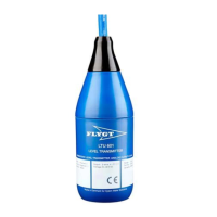
The document describes the Flygt LTU601 Level Transmitter, a submersible sensor designed for measuring liquid levels in various applications.
Function Description
The LTU601 is a level transmitter unit sensor that provides a standard 4-20 mA direct current signal output, proportional to the measured liquid level. It is designed for submerged measuring of liquid levels in open channels, drains, or tanks. The sensor operates reliably in both clean and heavily polluted, viscous fluids, making it suitable for applications such as pump stations, sewage plants, waterworks, and industrial process tanks.
Important Technical Specifications
Electrical Specifications:
- Measuring principle: Piezoresistive
- Supply voltage: 10-30 V DC
- Output signal: 2-wire 4-20 mA, passive transmitter
- Linearity / Stability: Better than ± 0.5% FS / ± 0.1% FS
- Measurement accuracy: Better than ± 0.25% FS @ 10–30 °C (50–86 °F); Better than ± 0.5% FS @ full temperature range
- Long time stability: Better than ± 0.5% FS per year
- Wiring:
- Red or white wire: Power + 10-30 V DC
- Brown wire: Signal/4 - 20 mA
- Black wire: Signal ground/shield (P/E connection)
Temperature Specifications:
- Process medium temperature: Nominal -10-60°C (14-140°F)
- Temperature deviation, zero point: Better than ± 0.02% / °C
- Temperature deviation, full range: Better than ± 0.02% / °C
Materials Specifications (Standard):
- Sensor body, including plastic encapsulation: Stainless steel 1.4404 AISI 316L, Polypropylene (PPS)
- Diaphragm: Stainless steel 1.4404 AISI 316 L
- Cable: 2 x 0.5 mm (0.078 x 0.02 in) (pressure), 5 x 0.15 mm (0.19 x 0.006 in) (data), shielded, Polyurethane rubber (PUR)
Approvals and Standards:
- CE conformity (EMC directive): In accordance with EN 61000-6-1:1999, EN 61000-6-2:1999, EN 61000-6-3:2001, EN 61000-6-4:2001
- Ingress protection rating: IP 68
Sensor Dimensions:
- Sensor body length: 167 mm (6.57 in)
- Sensor body diameter: 60 mm (2.36 in)
- Cable fitting length: 236 mm (9.29 in)
- Cable fitting diameter: 60 mm (2.36 in)
Measuring Ranges (Nominal, mWG):
- 0-2 m (0-6.56 ft)
- 0-3 m (0-9.84 ft)
- 0-5 m (0-16.4 ft)
- 0-10 m (0-32.81 ft)
Programmable Range:
- Minimum programmable range: 0-2 m (0-6.56 ft)
- Maximum programmable range: 0-12 m (0-39.37 ft)
- Maximum overpressure: 3 bar
Standard Cable Lengths for Measuring Ranges:
- 12 m (39.37 ft) cable for 0-3 m (0-98.4 ft) range
- 0-5 m (0-16.4 ft) range
- 0-10 m (0-32.8 ft) ranges
Usage Features
Mounting Configuration:
- The level sensor is submersible and, when free-hanging from the cable with a dedicated suspension attachment, is not position-dependent.
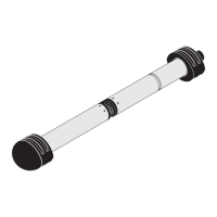
- For turbulent conditions, the sensor can be immersed in a pipe with a minimum inside diameter of 65 mm (2.56 in).
Installation:
- Carefully lower the sensor into the liquid media to ensure slow penetration of the surface. Avoid dropping it freely.
- Continue lowering until the sensor reaches its working position, which corresponds to the bottom of its range (≥ 4 mA). Do not exceed this depth.
- Secure the sensor to the cable holder where applicable.
Electrical Connection:
- Connect the red/white wire to Power + 10-30 V DC.
- Connect the brown wire to Signal/4-20 mA.
- Connect the black wire to Signal ground/shield (P/E connection).
Cable Extension:
- If the supplied cable length is insufficient, a junction box (Part number 839505) must be used for splicing due to the pressure equalization hose within the cable.
- A shielded cable should be used to guard against electrical disturbance.
- Signal cables should not be run near power cables.
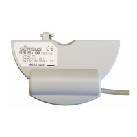
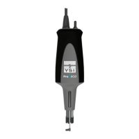
Accessories and Spare Parts:
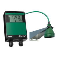
- Operator panel for level indication (Part number 834530)
- Junction box for cable with pressure equalization hose, including surge arrester (Part number 839505)
- Spare cable
- Spare cable holder (Part number 832174)
- Copper ring (Part number 834526)
- Non-standard cable lengths and measuring ranges are available as options.
Maintenance Features
Care and Handling:
- The LTU601 is robust due to its materials and design, making it tolerant of chemical and mechanical damage.
- Precautions should be taken to avoid corrosive media, over-pressure, and sharp impact.
Low pH Conditions:
- Acidic conditions (e.g., pH < 4) can reduce the sensor's lifespan. Contact a local sales and service representative for more information.
Cleaning:
- If necessary, carefully clean the sensor and rinse it with a mild detergent.
Mechanical Damage Prevention:
- Direct probing of the diaphragm can damage the sensor and void the warranty.
- Never drop the sensor into the liquid or allow it to fall freely.
Safety:
- Always read and understand the safety instructions before installation, operation, or maintenance.
- Ensure the unit and control panel are isolated from the power supply before any work to prevent electrical hazards.
- All electrical equipment must be properly grounded (earthed).
- All electrical work must be supervised by a certified electrician and comply with local codes and regulations.
- Visually inspect equipment for damaged cables, cracked casings, or other signs of damage.
- Prevent cables from becoming sharply bent or damaged.
- Only use manufacturer's original spare parts to avoid malfunctions, damage, injuries, and voiding the warranty.