EasyManua.ls Logo

Xylem FLYGT MRM 01 - User Manual

Xylem FLYGT MRM 01
20 pages
Print Icon
To Next Page IconTo Next Page
Loading...
Installation, Operation,
and Maintenance Manual
MRM 01
Question and Answer IconNeed help?

Do you have a question about the Xylem FLYGT MRM 01 and is the answer not in the manual?

Summary

Introduction and Safety

Manual Introduction

Overview of the manual's purpose and instructions for proper use and reference.

Safety Terminology and Symbols

Explains hazard levels, safety messages, and symbols to ensure user understanding of risks.

User Safety Precautions

Outlines general safety, electrical safety, and personnel qualification requirements for safe operation.

End of Life Product Disposal

Provides guidance on responsible disposal of the product and its components according to regulations.

Spare Parts Guidance

Emphasizes using original manufacturer spare parts to prevent malfunctions and warranty issues.

Warranty Information

Directs users to the sales contract for detailed information regarding product warranty.

Product Support

States that Xylem only supports tested and approved products, not unapproved equipment.

Transportation and Storage

Delivery Inspection

Procedures for inspecting packages and products for damage or missing items upon delivery.

Storage Guidelines

Recommendations for storing the product in a dry, covered location, protected from environmental factors.

System Description

Product Design Overview

Explains the MRM 01's role as an optional part of the MAS system and its connectivity.

Product Usage and Functions

Details how the MRM 01 is used for monitoring, relay output, and communication functions.

Mechanical Installation

DIN Rail Mounting

Step-by-step instructions for mounting the MRM 01 unit onto a standard DIN rail.

Electrical Installation

Explosive Zone Warning

Warning against installing the unit in environments with flammable or explosive gases or powders.

Unit Connection Procedures

Details how to connect relay outputs, Modbus communication, and power supply to the MRM 01.

CAS Replacement with MRM;MAS

Instructions for replacing a CAS unit with the MRM 01 and MAS base unit.

System Setup

MAS Base Unit Configuration

Guides users on configuring the MAS base unit, including alarms and relay modules via web interface.

DIP Switch Configuration

Explains how to set the MRM 01's DIP switches for relay functions and module address.

Technical Reference

Physical Dimensions

Provides the physical dimensions of the MRM 01 unit with a clear diagram for reference.

Environmental Requirements

Lists the operating temperature and humidity ranges suitable for the MRM 01 unit.

IP Rating

Specifies the Ingress Protection (IP) rating of the MRM 01 unit.

Electrical Data

Details electrical specifications such as supply voltage, frequency, and power consumption.

Approvals and Certifications

Lists the certifications and approvals obtained for the MRM 01 unit.

LED Functionality

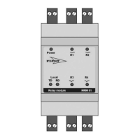
Explains the meaning and status indications of the LEDs on the MRM 01 unit.

Overview

The Flygt MRM 01 is a relay module designed to be an optional component of the MAS (Monitoring and Alarm System) base unit, enhancing its capabilities for pump monitoring and alarm management. Up to eight MRM 01 units can be connected to a MAS base unit via an RS-485 Modbus connection, allowing the MAS to communicate individual alarms from separate monitoring channels to the relays and LEDs on one or more MRM units.

Function Description:

The primary function of the MRM 01 is to provide separate indication and relay outputs for each monitoring channel, similar to how a CAS (Control and Alarm System) operates. Pump sensors are connected to the MAS base unit, which then monitors the pump and detects unhealthy conditions. Individual alarms detected by the MAS are transmitted to the LEDs and relays on the MRM 01.

The configuration of which alarm triggers which relay on which MRM is managed through the MAS embedded webpages. This includes sensor configuration, alarm limits, and other settings. When no specific settings are applied, the MAS and one MRM 01 are preconfigured to replace a CAS.

The MRM 01 offers several usage features:

  • CAS Replacement: When complemented with a MAS, the MRM 01 enables separate indication and relay output for each monitoring channel, making the system fully compliant as a CAS replacement. This is particularly useful for upgrading existing systems.
  • Language Independent Monitoring: For large pumps, a MAS base unit combined with two or more MRM 01 units can replace the text screen of an operator panel, providing a language-independent monitoring solution. The LEDs on the relay modules allow for easy distinction between alarm channels. The output relays can be connected to external control panel lamps, with configuration managed via the MAS embedded webpages.
  • PLC Communication Alternative: The MRM 01 can serve as an alternative to serial communication between the monitoring system and a PLC (Programmable Logic Controller). Up to eight MRM units can be configured to transmit alarms, with setup performed through the MAS embedded webpages.

Important Technical Specifications:

  • Dimensions:
    • Width: 60 mm (2.4 in)
    • Depth: 53 mm (2.1 in)
    • Height (overall): 116 mm (4.6 in)
    • Height (from DIN rail): 86 mm (3.4 in)
  • Environmental Requirements:
    • Operating temperature: -20°C to +60°C (-4°F to 140°F)
    • Operating humidity: Relative humidity, non-condensing: 85%
  • IP-rating: IP 20
  • Electrical Data:
    • Supply voltage: 24 V AC or DC
    • Frequency: 45 Hz to 65 Hz
    • Supply voltage tolerance: ±10%
    • Supply dropout: 50 ms without function disruption
    • Relays: Four relays, 5 A, 250 VAC, normally opened
    • Power consumption: 24 VDC maximum: 3 VA; 24 VAC maximum: 6 VA
  • Connections:
    • Relay Outputs:
      • Output relay 1: 5 A, 250 VAC (Terminals 3, 4)
      • Output relay 2: 5 A, 250 VAC (Terminals 1, 2)
      • Output relay 3: 5 A, 250 VAC (Terminals 9, 10)
      • Output relay 4: 5 A, 250 VAC (Terminals 7, 8)
    • Modbus Communication:
      • Modbus/RS-485 (B) to MAS terminal 38 (MRM 01 Terminal 11)
      • Modbus/RS-485 (A) to MAS terminal 37 (MRM 01 Terminal 12)
    • Power Supply:
      • 24 VAC or 24 VDC (MRM 01 Terminal 5)
      • Ground (MRM 01 Terminal 6)
  • Approvals: CE, CSA/US

Usage Features:

  • DIN Rail Installation: The unit is designed for easy installation on a DIN rail. The process involves hooking a lip at the back of the unit onto the top of the DIN rail and then pressing the unit down until the rail clip snaps into place.
  • LED Functions: The MRM 01 features several LEDs to indicate its status and the status of the monitored channels:
    • Power LED:
      • Blinking: Indicates a communication error with the MAS base unit.
      • Lit: Indicates power is on and communication with the MAS base unit is established.
    • RD (Receive Data) LED: Indicates RS-485 or Modbus communication with the MAS base unit.
    • TD (Transmit Data) LED: Indicates data transmission.
    • R1-R4 (Relay Status) LEDs: These four LEDs correspond to the individual relay channels.
      • Lit or Blinking: Indicates the related relay is active.
      • Blinking: Indicates an alarm.
      • Lit: Indicates OK or acknowledged status.
  • System Setup:
    • Activating Communication Alarm: The communication alarm for relay modules can be activated via the MAS web tool under "Setup > General configuration > RS-485/Modbus." The "Communication alarm" status for "Relay modules (Local)" should be set to "On," and changes updated.
    • Setting up MAS Relay Module: Configuration of the relay modules is done through the MAS web tool under "Setup > General configuration > Relay Modules, MRM 01." This includes activating the module and setting the "Action priority" for each relay based on the monitoring channel.
    • DIP Switches: The MRM 01 has DIP switches for setting the address of the relay module and defining individual relay functions.
      • Switches 1-2: Used for setting individual relay functions (e.g., relay closes on alarm, relay opens on alarm). By default, DIP switches are off, meaning the relay closes when there is an alarm. To make the relay open when there is an alarm, the corresponding DIP switch should be set to ON.
      • Switches 5-8: Used for setting the Modbus address of the relay module. The address is set by combining the ON/OFF positions of these switches.

Maintenance Features:

  • Spare Parts: Only original manufacturer's spare parts should be used for replacement to prevent malfunctions, damage, injuries, and to maintain warranty validity.
  • Disposal: The product and its batteries must be disposed of in compliance with local laws and regulations, following WEEE Directive guidelines for electrical and electronic equipment and Directive 2006/66 for batteries. This ensures environmental protection and promotes material reuse.
  • Safety Precautions:
    • Always read and understand the safety instructions before working on the unit.
    • Ensure the unit and control panel are isolated from the power supply and cannot be energized before starting work.
    • All electrical equipment must be grounded (earthed) correctly.
    • All electrical work must be supervised by a certified electrician and comply with local codes and regulations.
    • Visually inspect equipment for damaged cables, cracked casings, or other signs of damage.
    • Prevent cables from becoming sharply bent or damaged.
    • Do not install the unit in environments containing flammable/explosive or chemically aggressive gases or powders.
    • This product is not an emergency stop device; an external switch or circuit breaker must be provided near the installation for power isolation.

The MRM 01 is designed for reliability and ease of integration into existing or new Flygt MAS systems, providing robust monitoring and alarm capabilities for various pump applications.

Xylem FLYGT MRM 01 Specifications

General IconGeneral
BrandXylem
ModelFLYGT MRM 01
CategoryRelays
LanguageEnglish