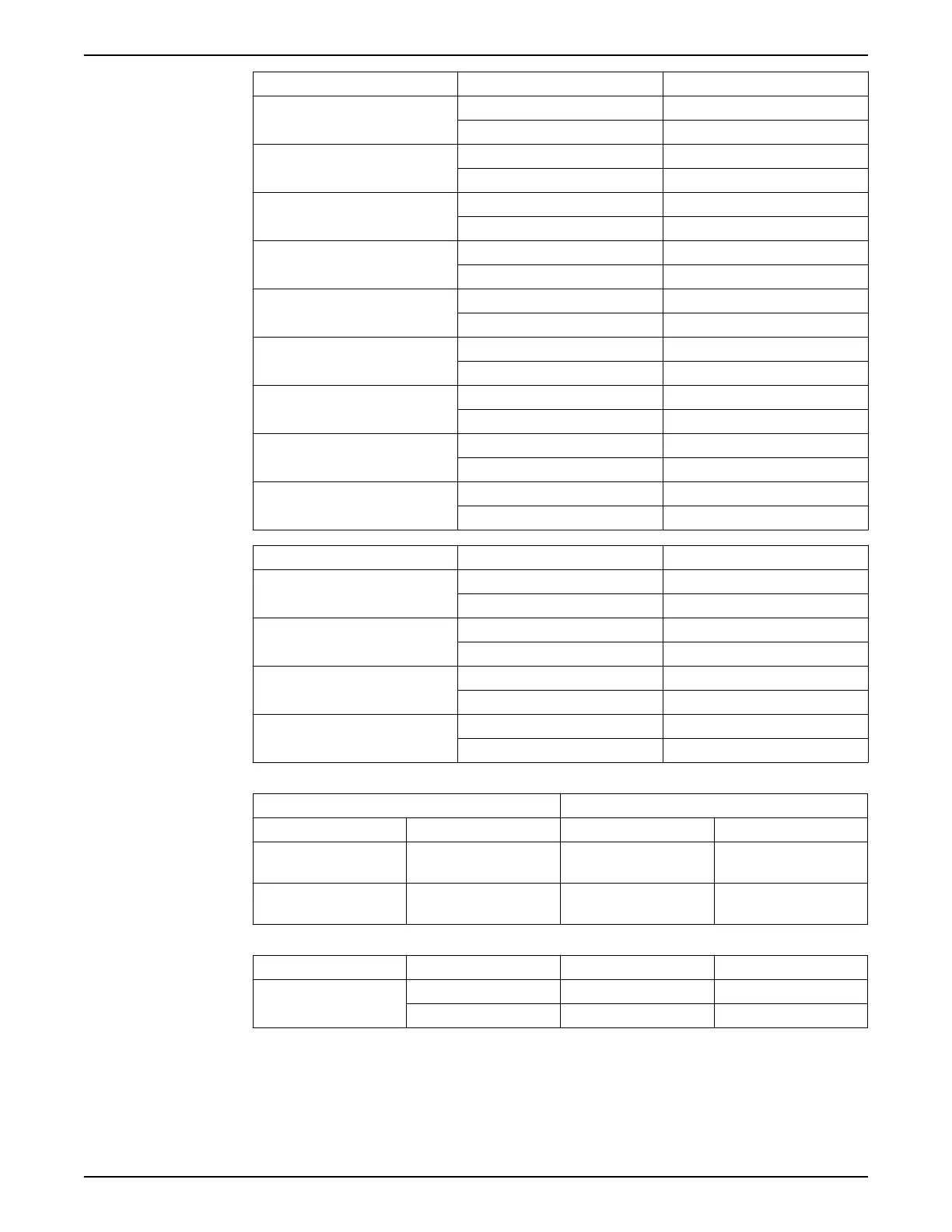
CAS description CAS terminal MAS base unit terminal
CAS A: Liquid level sensor (Stator
housing)
17 13
18 14
CAS B: Oil flow or liquid level sensor 19 15
20 14
Reset 22 22
23 23
RUN (used only together with the oil
flow sensor)
24 24
25 23
CAS C: Winding over temperature
protection
26 1
27 2
Pt100 sensor 28 8
29 4
Option to read Pt100 temperature
value
31 20
32 21
CAS Σ: Output for remote indication
24 V / max 2 VA
8 31
9 32
Interlock contact, Max 240 V / 4 A 11 27
12 28
CAS description CAS terminal MRM 01 terminal
CAS A: Output for remote indication
24 V / max 2 VA
1 3
2 4
CAS B: Output for remote indication
24 V / max 2 VA
3 1
2 2
CAS C: Output for remote indication
24 V / max 2 VA
4 9
5 10
CAS D: Output for remote indication
24 V / max 2 VA
6 7
7 8
3. Connect the Modbus communication between the MAS base unit and the MRM 01.
MAS base unit MRM 01
Description Terminal Description Terminal
Local, RS-485 (A) (Modbus
master)
37 Modbus/ RS-485 (A) 12
Local, RS-485 (B) (Modbus
master)
38 Modbus/ RS-485 (B) 11
4. Connect the power supply to the MAS base unit and the MRM 01.
CAS description CAS terminal MAS base unit terminal MRM 01 terminal
24 VAC supply 14 25 5
16 26 6
5 Electrical Installation
10 MRM 01 Installation, Operation, and Maintenance Manual