en - Original instructions
38
level Float
switch
- Maximum
- S MAX
- Level
Probe
- S 1
switch
Pump 1
- Common
Probe
- Multiwire
probe ca-
(1)
- S COM
- S MIN
- S 1
- S MAX
level Float
switch
- Minimum
- S MIN
4.5.4
Q-SMART 20/SE sewage
drain/filling set
Refer to figures 5, 7 and 9
(Figure
5)
ection
(Figures 7, 9)
phy Q-
SMART
(Figures
cable diame-
ter (mm)
probe ca-
ble
(1)
- Multiwire
float
switch ca-
ble
(1)
- S MIN
- S 1
- S 2
- S MAX
- G 1
- G 2
- Minimum
level Float
switch
4.6
POWERING THE ELECTRIC PUMPS
IN AN EMERGENCY
In case the software or electronics of the Q-
SMART control panel is blocked, the pumps can
be powered by changing the position of the jumper
switches M1 and M2 (refer to figures
7 and 10).
• Make sure that this operation is
performed by qualified installation
technicians and in compliance with
the regulations in force.
• Before starting work on the unit, make
sure that the unit and the control panel
are isolated from the power supply
and cannot be energised.
• This operation must be carried out
only in the case of emergency.
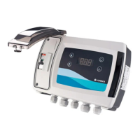
5 System Description
5.1 User interface
The list describes the parts in Figure 1.
1 and 2
1 = Button for running the electric pump
1. Press and hold the button to run.
2 = Button for running the electric pump
2. Press and hold the button to run.
In STANDBY (StY) mode:
1,2 Increasing or de
value of a parameter selected in
3
Type of display:
Three digit LEDs with light symbols
4
Button for switching between the
operating modes:
• AUTOMATIC (Aut)
• MANUAL (MAn) and
• STANDBY (StY) (enable pro-
5
Button for confirming the menu and
data.
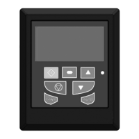
5.2
Display information
This list describes the parts shown in figure 2.
1
Green-lighted LED, indicating that
pump 1 is running
2
Blue-lighted LED, indicating AUTO-
MATIC mode
3
Green-lighted LED, indicating that
pump 2 is running
4
Red-lighted LED, indicating a fault.
The LED is illuminated when there is
Yellow-lighted LED in MANUAL mode
 Loading...