en - Original instructions
39
6
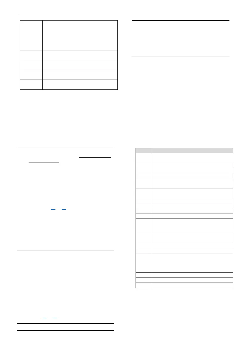
Red-lighted LED indicating:
•
Lack of water alarm ON, for
booster application
or
• High level alarm ON, for sew-
7
Red-lighted LED indicating Tem-
perature °C, if selected
8
Red-lighted LED indicating head
(water column) in m, if selected
9
Steady green-lighted LED, indicating
the power is on
10
Red-lighted LED indicating pressure
in bar, if selected
5.2.1 Locking/unlocking the user inter-
face
The buttons (4) are enabled in AUTOMATIC or
MANUAL mode and allow the user to view the
operation and alarms log (see section
5.4.2) or to
access the menus and edit the operating parame-
ters (see section
5.4.3).
5.3 Start-up and programming
• If supplied individually,
SOFTWARE IS:
- SEWAGE (SE) for Q-SMART10../D, Q-
SMART20../D, see section 3.2 and
5.4.3 tab. 2
- PRESSURISATION (bS) for Q-
SMART10../B, Q-SMART20, see sec-
tion 3.2 and
5.4.3 tab. 3.
Edit the values according to the type of elec-
tric pump and system, see section
5.4.4 and
refer to figures 11 to 64
.
• When the control panel is already connect-
ed to an electric pump or a booster set, the
same has been programmed based on the
characteristics of the electric pump, and the
default values may change. Edit the function
values of the system.
• Incorrect configuration can damage the
electric pump and/or the system.
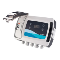
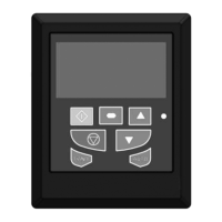
Refer to figures
1 and 2 for the user interface.
1. Check that all the mechanical, electrical and
hydraulic connections have been made. See
Mechanical installation section
4.2, Electrical
installation section 4.3.
2. Turn on the power at the main switch (1) fig-
ure
7 and the control panel starts up.
3. The control panel performs an internal hard-
ware Auto-test and the LED (9) turns on. It is
possible to enter the CONFIGURATION
MENU to set the proper application (refer to
figures 11 to 6
4).
• Start-up mode after a shutdown is always
AUTOMATIC, and cannot be changed.
• In automatic mode, the electric pump runs if
the pressure, level or temperature of the
system is below the value selected. If nec-
essary, press (4) to set MANUAL mode and
the electric pump turns off if running.
The parameters in the PARAMETER menu can
be edited ONLY in STANDBY (StY) mode. Press
(4) to switch between AUTOMATIC or MANUAL and
STANDBY (StY) mode; the LEDs (5) and (2) are off.
See section
5.4.4 for the proper procedure.
5.4 Programming
The control panel has three menus that can be
accessed with a combination of keys:
• QUICK CONFIGURATION (see section 5.4.3)
• ALARMS LOG (see section
5.4.2).
• PARAMETERS (see section 5.4.4).
5.4.1
Texts shown on the display
MAn
Operation Manual mode: pump is
stopped
Operation Automatic mode.
Standby mode: Programming is enabled
Software selection (sE or bS)
SE
The Q-SMART control panel is set in
SEWAGE mode.
bS
Q-SMART control panel is set in Pres-
surisation BOOSTER mode.
Adjustment parameter menu
---
Shown on display when the analogue
sensor is not used. The digital sensor is
run
When the analogue sensor is not used
(no feedback), the pump is running
OFF
Q-SMART control panel is disabled by
the external command switch connect-
ed to the D IN PROGR (figure
9)
The status of the alarm in the alarm log.
The status of the alarm in the alarm log.
5.4.2
Alarm log
It is possible to view information concerning any
alarms in either MANUAL or AUTOMATIC mode.
The menu is read-only and displays the last 20
alarms that have occurred.
Refer to figures
1 and 2.
 Loading...