
M
Michael ReedAug 18, 2025
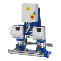
Why Xylem LOWARA SMB /SVE motor does not start?
- BbaileydebbieAug 19, 2025
The motor of your Xylem Extender might not be starting due to several reasons: a cut-off in the power supply, which would require restoring the power; triggering of the motor's thermal overload protection, in which case you should eliminate the fault and reset the switch; or a faulty motor coil, necessitating a check, repair, or replacement of the motor.