en – Original instructions
28
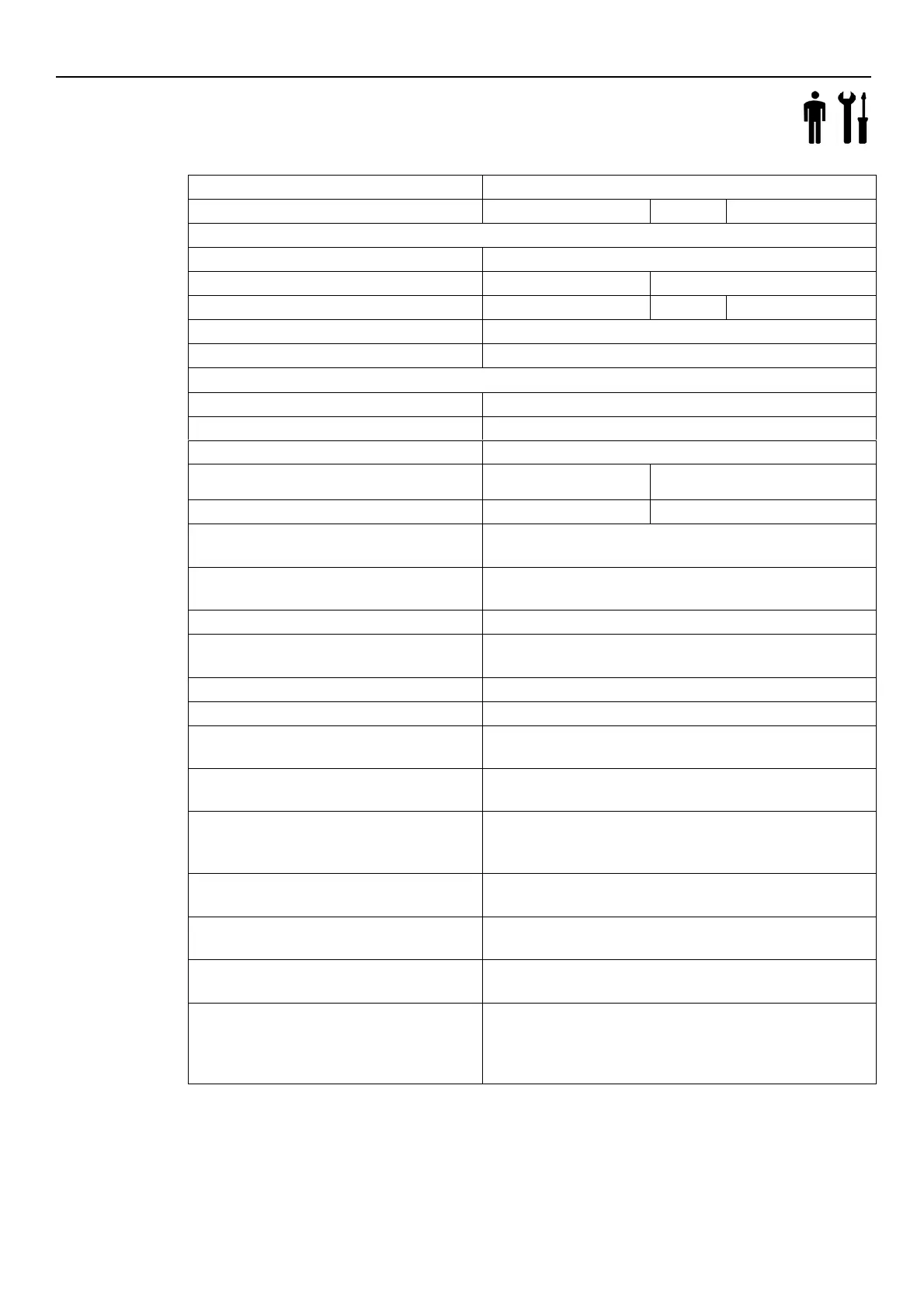
8 Technical Data
Table 2: Electrical, environmental and installation specifications, booster set in standard version
Control panel power supply
Nominal input voltage of the control panel [V]
Max. Input Current Continuous [A]
Refer to the data plate of the control panel
Max power of control panel [kW]
Refer to the data plate of the control panel
Min-max speed for pump unit [rpm]
Leakage current for inverter [mA]
I/O auxiliar + 15VDC power supply [mA]
1 x NO Vmax < 250 [VAC] , Imax
< 2 [A]
1 x NO Vmax < 250 [VAC] , Imax < 2 [A]
1 x NO Vmax < 250 [VAC] , Imax < 2 [A]
Sound pressure LpA [dB(A)] @ [rpm]
IP 55, Enclosure Type 1
Protect the product from direct sunlight and rainfall
Water temperature [°C] / [°F]
Relative humidity in relation to the operating
temperature [°C] / [°F]
5% - 50% RH @ 40 / 104
5% - 90% RH @ 20 / 68
Relative humidity for storage
Storage temperature [°C] / [°F]
Operating temperature
[°C] / [°F]
Installation altitude a.s.l. [m] / [ft]
< 1000 / 3280
Derating may occur at higher altitudes
Max operating pressure [bar]
8, 10 or 16, depending on the type of pump unit. Refer to the
Installation, Operation and Maintenance Manual of the pump unit
in the Smart Pump Range.
According to NPSH curve with a margin of at least 0.5 m for air-
free water
Make sure the inlet pressure plus the closed delivery pressure
does not exceed the maximum operating pressure
General data of the pump unit
Refer to the Installation, Operation and Maintenance Manual of
the pump unit in the Smart Pump Range
Diaphragm pressure tank [bar]
Refer to the standard Installation, Operation and Maintenance
Manual of the diaphragm pressure tank. Installed diaphragm
pressure tanks can limit the temperature and operating pressure
of the booster set
 Loading...