Do you have a question about the Yaesu FTM-7250DR and is the answer not in the manual?
Explains DANGER, WARNING, CAUTION marks and safety symbols.
Explains prohibited and required action symbols for safe product use.
Lists critical safety warnings for usage locations, conditions, and electrical hazards.
Lists safety warnings regarding power supply, heat, electrical shock, and handling.
Procedure to power the transceiver on and off using the PWR/LOCK key.
Using the MHz(SETUP) key to select frequency bands like AIR or 144/430 MHz.
Using the MODE(DG-ID) key to switch between AMS, V/D, Voice FR, and Analog FM modes.
Configuring AUTO, TXMANUAL, TX FMFIX, TX DIGTL, TX VWFIX transmission modes.
Steps for transmitting using the PTT switch and microphone.
Selecting HIGH, MID, or LOW power levels using the D key.
Setting the transceiver's call sign for digital communication identification.
Using the DIAL knob or microphone keys to change frequency.
Activating/canceling the key-lock feature using the Power(Lock) key.
Using the VOL knob to set the receiver volume.
Using the DIAL knob and BAND(SQL) key to set the squelch level.
Explains DG-ID for group communication and repeater access.
Step-by-step guide to storing DG-ID numbers and tags in memory.
Procedure to recall and display stored DG-ID information.
Describes DP-ID for individual transceiver identification in C4FM digital mode.
Steps to register other transceivers' DP-IDs into the list.
Process to remove registered DP-IDs from the list.
Utilizing the Automatic Repeater Shift (ARS) function for repeater communication.
Instructions for receiving NOAA weather broadcasts on preloaded channels.
Explains registering DP-ID for remote control of DR-2X repeaters.
Step-by-step guide to storing frequencies and modes into memory channels.
How to access stored memory channels using VFO mode or DIAL knob.
Direct recall of memory channels using the microphone keypad.
How to start, stop, and pause scanning using microphone keys.
Restoring factory defaults for all settings and memories.
Clearing all memories and settings to factory defaults.
Resetting only Setup Menu settings to factory defaults.
Displays node status if disconnected from other nodes/rooms.
Registering node/room IDs (C1-C5) to memory.
Steps for connecting and communicating using DTMF signals in analog mode.
Steps for connecting to a WIRES-X node using DG-ID.
Displays node status upon successful connection to internet.
Deleting registered node/room IDs from memory.
Procedure to disconnect from a WIRES-X node or room using a DTMF command.
Procedures for connecting to different node or room IDs.
Interface for direct connection via manual input of node/room ID.
Transmitting DTMF codes via microphone or memory recall.
Sets the magnitude of the Repeater Shift.
Sets the Repeater Shift direction.
Programs Alpha/Numeric labels for memory channels.
Selects channel selection method for memory storage.
Sets the transmission mode (AUTO/TXMANUAL/TX FMFIX/TX DIGTL).
Turns the VW mode selection ON or OFF.
Manages DP-ID list (Display/Register/Clear).
Programs function assigned to the microphone [P3] key.
Programs function assigned to the microphone [P4] key.
Enables/Disables the Weather Alert feature.
Activates/Deactivates the Automatic Repeater Shift feature.
Sets the WIRES-X DG-ID.
Step-by-step guide for replacing a blown fuse in the DC power cable.
| Brand | Yaesu |
|---|---|
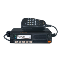
| Model | FTM-7250DR |
| Category | Transceiver |
| Language | English |