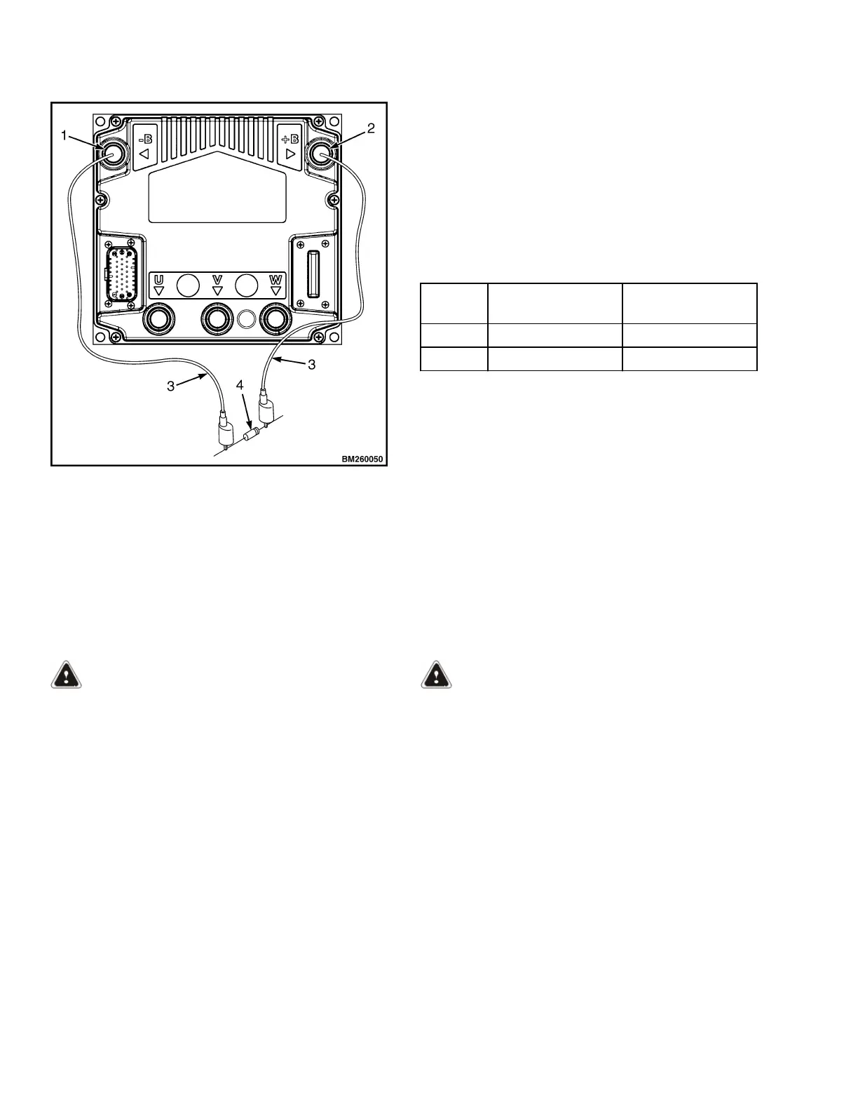
Figure 1. Discharging the Capacitors
Legend for Figure 1
1. B- TERMINAL
2. B+ TERMINAL
3. JUMPER LEADS
4. 200-OHM, 2-WATT RESISTOR
6. Remove the resistor from the controller and
reinstall the electrical compartment cover before
returning the lift truck to service.
Type
DC Battery
Voltage
AC RMS
Current Rating
ACE0 24 320
ACE0 36 280
Parameters
A parameter is a measurement or a setting that de-
fines a lift truck function. A specific function parameter
works with other function parameters to control the
operation of the lift truck.
WARNING
The parameter for each function has a value range
so the motor controller can be used on different
models of lift trucks. This variation is needed for
lift trucks of different capacities and operational
needs. Adjustment of a function to the wrong
number value for your lift truck model can cause
the truck to operate differently than normal. Al-
ways test operational characteristics of a lift truck
when operating for the first time.
NOTE: Table 1 and Table 2 show the factory default
settings and total range for each parameter that is ad-
justable by the user.
Parameters can be adjusted through the dash display.
If the lift truck is equipped with Dash Software v3.0
see Table 1. If the lift truck is equipped with Dash
Software v3.02 see Table 2. The factory default val-
ues listed in Table 1 and Table 2 are the recommen-
ded settings for new units. These settings will give
satisfactory performance for most applications.
WARNING
If any of the parameter values are changed, the
operators must be told the lift truck will operate
differently.
NEVER adjust any of the following parameters
without using the procedures and settings given
in this section.
Parameter Descriptions in this section contains de-
scriptions for the different parameters. These parame-
ters can also be accessed using the ZAPI Handset
tool.
Parameters 2200 YRM 1415
2
 Loading...