19
Components
EMU2579H
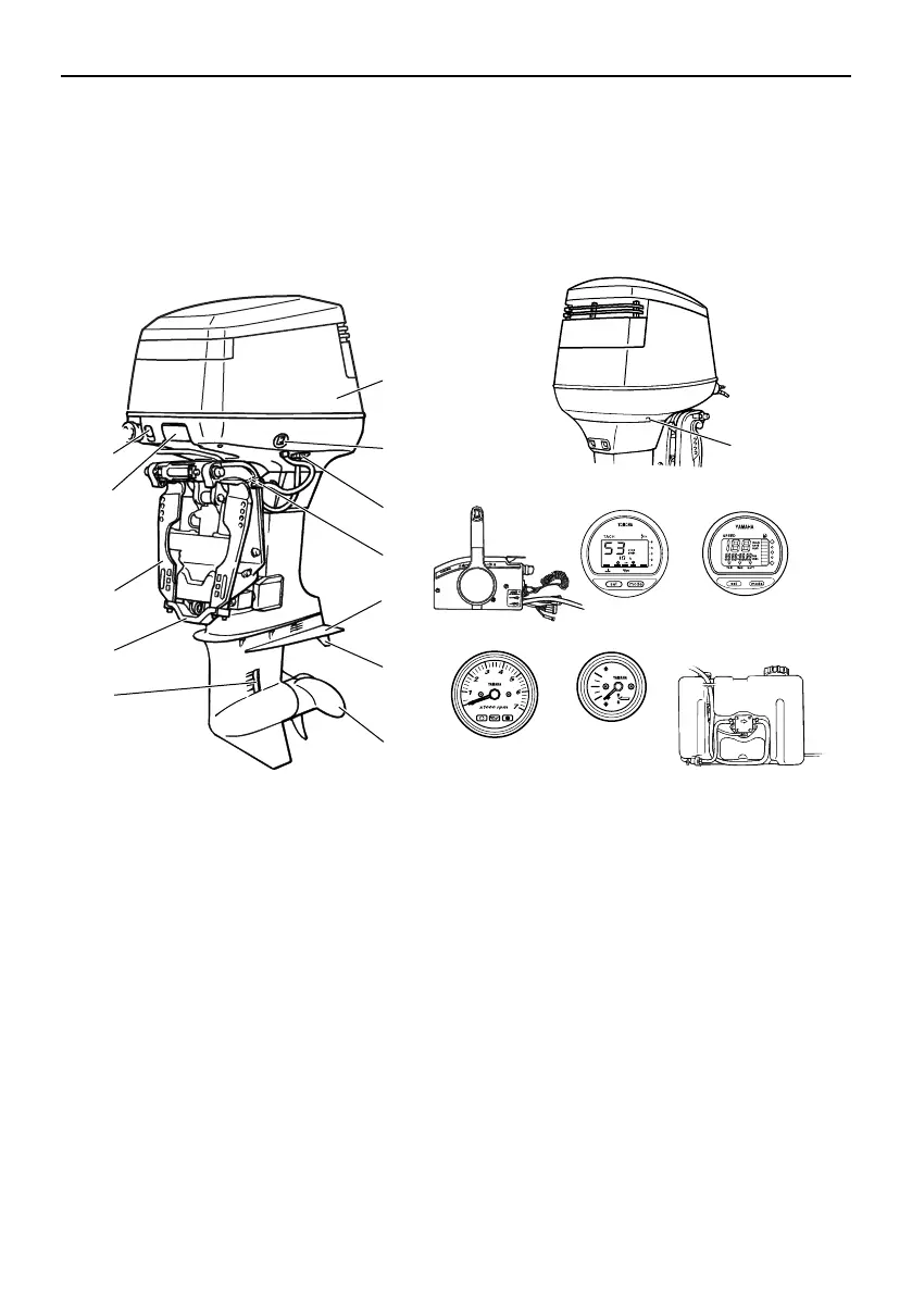
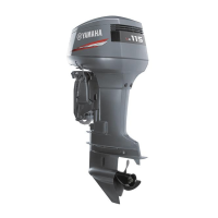
Components diagram
IP:
* May not be exactly as shown; also may not be included as standard equipment on all mod-
els.
115
EMU26181
Remote control box
The remote control lever actuates both the
shifter and the throttle. The electrical switch-
es are mounted on the remote control box.
4
7
8
9
10
1
2
3
5
6
12
11
13
14 15 16
17 18
19
ZMU04764
1. Top cowling
2. Power trim and tilt switch
3. Flushing device
4. Tilt support lever
5. Anti-cavitation plate
6. Trim tab (anode)
7. Propeller*
8. Cooling water inlet
9. Anode
10. Clamp bracket
11. Top cowling release lever
12. Choke knob
13. Cooling water pilot hole
14. Remote control box (side mount type)*
15. Digital tachometer*
16. Digital speedometer*
17. Tachometer*
18. Trim meter*
19. Remote oil tank*