2-14
Outboard Rigging Guide - 2001 Jet Drive Eng. Mtg., Maintenance,
Shift Cable Instruction, Service Info.
3. Make two diagonal braces from 1/2" electri-
cal conduit. Flatten each end in a vise, and
drill 1/4" holes in them. Determine the posi-
tion and angle of the forward bend. Attach
them to the boat in a solid location, such as to
the seats or gunwales. Avoid attachment to
flexible aluminum panels.
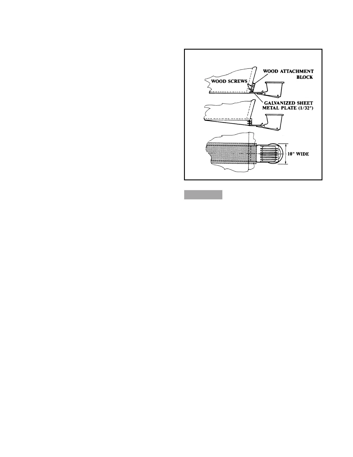
Anti-Cavitation Plates
To reduce spray or to further reduce cavitation in
rough water, a 1/32" - thick metal plate can be
installed to block the entrance of air into the water
in front of the jet drive intake scoop. Installation
of this plate will also allow a slightly higher motor
mounting point, which, of course, will reduce
drag.
The position for proper mounting is shown in the
first part of the accompanying illustration.
An alternate mounting position for the plate (with
the plate attached to a keel or wedge for use in
“white water”) is shown in the second and third
parts of the illustration. The third part shows the
width of the plate, as well as the width of the
drop-bottom wedge that positions the intake in
more solid water. This installation, however,
reduces shallow-water capabilities and should be
used only when necessary.
After any of these procedures are undertaken,
the motor height and tilt settings should be
checked and reset (as necessary) to avoid
excessive cavitation that could lead to impeller
damage.
NOTE: Either of the above modifications should
utilize only marine-grade woods; silicon-base,
waterproofing sealing compounds (between com-
ponents and around screws); and marine-grade
paints. Remember, once you adopt one of these
modifications, if removed or changed, damage
may result to your hull if precautions are not taken
to fill and/or waterproof any holes.
 Loading...