Do you have a question about the Yamaha A4000 and is the answer not in the manual?
Explains Yamaha electronic product safety labels and their meanings.
Details Yamaha's commitment to user safety and environmental friendliness.
Information regarding the product's internal battery, its lifespan, and handling.
Indicates the location of the name plate with model and serial information.
Basic safety precautions to avoid injury, damage, fire, or hazards from electrical shock.
Basic precautions to avoid physical injury or damage to the instrument or property.
Advice on protecting data against loss and saving it regularly.
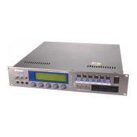
Overview of the A5000/A4000's capabilities for music production.
Details on the number and type of effect blocks available.
Highlights the user-friendly LCD panel and intuitive controls for easy operation.
Information on options for expanding memory and I/O capabilities.
Outlines the manual's structure into chapters covering setup, basics, system, and commands.
Describes methods for locating specific information using TOC, Index, and Function Tree.
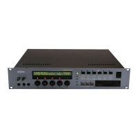
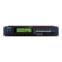
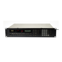
Details the MASTER VOL, REC VOL, PHONES jack, INPUT jacks, display, and knobs.
Explains the Function buttons, COMMAND/EXIT, ASSIGNABLE, and AUDITION buttons.
Describes rear panel connectors including AC inlet, MIDI, ASSIGNABLE OUT, STEREO OUT, and SCSI.
Details OPTICAL and DIGITAL I/O connectors added by the AIEB1 board.
Information on increasing sampling memory capacity with SIMM modules.
Details on required SIMM specifications and installation pairs.
Adds digital I/O capabilities and extra assignable outputs.
General advice for handling floppy disks and the drive with care.
Step-by-step instructions for inserting and ejecting floppy disks.
Guide to setting up equipment and performing a sound check.
Instructions for connecting the power cord to the unit and outlet.
Explains how to connect the sampler's audio outputs to external devices.
Details connecting microphones and other sound sources.
Introduces basic MIDI concepts and connection methods.
Explains the correct sequence for powering equipment on and off.
Guides through a sound check to confirm proper connections and operation.
Covers fundamental concepts: recording, editing, and playback.
Provides step-by-step guides for key sampling, editing, and playback operations.
Explains removing unwanted parts and setting samples to loop for sustained playback.
Using filters for timbre modification and EGs/LFOs for sound variations over time.
Assigning samples to programs for playback via keyboard or MIDI controller.
Using the sampler's extensive effects to enhance the sound.
Assigning controller functions for real-time expression control.
Instructions on connecting microphones or line sources to the sampler's inputs.
Guides the user to access the REC-RecSetup display for recording configuration.
Details selecting the appropriate input source (AD L, AD L/R, DIGITAL, OPTICAL).
Details selecting the sampling frequency for optimal quality and memory usage.
Explains setting the pre-trigger time to capture the beginning of samples.
Explains setting the analog input gain for microphones or line-level signals.
Guides the user to the EDIT-Waveform display for trimming.
Details setting the start and end points for trimming the waveform.
Guides the user to the EDIT-Waveform display for looping.
Instructions on selecting a sample from the list for editing.
Details setting the start and end addresses for precise loop points.
Introduces functions like Length Lock, Zero, and Snap for easier loop point setting.
Guides the user to the EDIT-Mix&Key display for mapping.
Instructions on selecting a sample for editing.
Details setting the original key, low, and high notes for the sample's playback range.
Guides the user to the EDIT-Fltr&EQ display for filter setup.
Details setting filter type, cutoff frequency, and Q/Width for various filter modes.
Introduces setting up envelope generators for amplitude, filter, and pitch.
Guides the user to the EDIT-AmpEG display for amplitude envelope setup.
Details adjusting the amplitude envelope parameters (Attack Rate, Decay Rate, Sustain Level, Release Rate).
Introduces setting up the Low Frequency Oscillator for modulation effects.
Guides the user to the EDIT-LFO display for LFO setup.
Details setting the LFO waveform, speed, initial delay, and key synchronization.
Accesses the PLAY-PgmSel display for program selection.
Explains selecting a program for playback or editing.
Guides the user to the PLAY-SmpSel display for sample selection.
Encourages playing the program from a keyboard, sequencer, or controller.
Summarizes the tutorial and directs to the reference section for more details.
Provides an overview of the sampler's system structure and basic operating procedures.
Details the organization of functions into modes and commands.
Explains common display features and how to select modes, functions, and edit parameters.
Outlines the main components: tone generator, effect stage, EQ, controllers, sequencer, and I/O interface.
Explains the core component for audio recording and playback via MIDI controller.
Details the effect section for adding ambience and modifying output signals.
Explains sample banks as groups of related samples for managing instruments or drum kits.
Divides program data into Sample Select, Easy Edit, and Program Parameters.
States the maximum polyphony for the A5000 and A4000 models.
Details how sample output destinations determine routing to effect blocks.
Describes how effect blocks can be connected in series, parallel, or combined.
Describes the basic sequencer for recording performance data and musical phrases.
Explains the relationship between internal memory and disk storage for data management.
Describes how samples, banks, programs, and parameters are stored in memory.
Defines disks and explains formatting and partitioning requirements.
Explains volumes as virtual containers for data storage on disks.
Provides page references for executing various save and load operations.
Explains function grouping into modes (PLAY, EDIT, RECORD, UTILITY) and commands.
Describes PLAY mode for playing and editing programs, listing its six functions.
Covers selecting MIDI channels and setting controller response for samples.
Specifies how recording will be started and stopped.
Specifies "record effects" to be applied to the recorded signal.
Controls playback of an external audio CD.
Sets up monitoring of the source signal and click signal generation.
Selects volumes for saving/loading data, renaming, creating, and loading.
Allows disk selection, renaming, mounting/unmounting, and SCSI ID setting.
Imports sample and sequence data from other equipment and computers.
Sets up the 4-band equalizer for stereo output signals.
Sets up knobs as MIDI controllers and function keys as MIDI keyboard keys.
Records and replays MIDI sequences.
Adjusts system pitch, stereo output level, and assignable output destination.
Sets up system operating environment and screen-display options.
Accesses functions affecting MIDI operation.
Copies programs or samples (sample banks) to different locations.
Deletes specified samples (sample banks) or sequences from memory.
Saves specified data from memory to disk.
Automatically rearranges sample mapping for programs or sample banks.
Applies Easy Edit or Sample Bank settings directly to samples.
Registers initial EFFECT, SETUP, and CONTROL settings.
Transfers program and sample data via MIDI bulk dump.
Initializes one or all memory-resident programs.
Includes sample normalization, reverse, fade, and loop crossfade commands.
Divides wave data between loop points into independent segments.
Applies time stretch and pitch conversion to samples.
Converts stereo samples to mono.
Moves samples between programs, sample banks, or both.
Creates basic oscillator waveforms: sine, saw, triangle, square, pulse.
Converts selected samples to AIFF or WAV format and saves to disk.
Restores selected sample or sample bank to previously saved version.
Explains common display elements like mode/page indicators, knob functions, and sample name displays.
Guides on how to select modes and functions using mode buttons and function buttons.
Describes using mode and function buttons to select display pages or move the cursor.
Explains how to engage functions indicated by labels above knobs.
Describes how to move the cursor using Knob 2 to select character locations.
Details selecting characters using Knob 3 and changing types with Knob 4.
Explains entering a character and moving the cursor.
Describes entering a space or erasing a character.
Explains setting parameters like MIDI channels via receiving MIDI messages.
Describes the Tree View display for convenient sample selection and MIDI input selection.
Explains the symbol indicating samples assigned to the current program.
Shows the MIDI receive channel assigned to samples/banks.
Displays the original key note of the sample.
Shows the actual playable range of a sample based on program transpose and easy edit.
Explains passing analog signals through the sampler for program play, with effects.
Explains how blinking mode button lamps indicate received MIDI data types.
Details the [COMMAND/EXIT], [ASSIGNABLE], and [AUDITION] buttons.
Instructions for restoring the sampler to its factory preset status.
Details entering the PLAY mode and the concept of a "program".
Lists the six functions within PLAY mode: PROGRAM, SAMPLE, EASY EDIT, EFFECT, SETUP, CONTROL.
Guides on selecting programs, setting program mode, and basic MIDI channel.
Explains the Single mode where one program functions as a tone generator.
Details settings for multi-timbral programs.
Details Program Mix settings for single programs.
Details Program Mix settings for multi-timbral programs.
Details portamento settings for single programs.
Details portamento settings for multi-timbral programs.
Assigns samples to programs, selects for editing, or saves to disk.
Enables or disables the "sample solo" feature for isolating sample playback.
Sorts sample names according to specified conditions.
Positions cursor to select shortcut commands like DUPLICATE, DELETE, SAVE, RENAME.
Positions cursor to select the sample bank to be edited.
Selects the highlighted sample for editing.
Sorts sample names according to specified conditions.
Positions cursor to select the sample to be edited.
Selects the highlighted sample for editing.
Removes or adds selected samples to/from a sample bank.
Adjusts the sample's level and pan settings.
Sets output destination and level for Output 2, and filter gain.
Adjusts sample's pitch, including coarse, fine, fixed, random pitch, and portamento.
Determines how quickly the sound reaches maximum level.
Sets the rate at which the sound decays to the sustain level.
Sets the rate at which amplitude drops after Note Off.
Applies an offset to the original key, low key, and high key parameters.
Sets the minimum velocity required for sound production.
Sets the maximum velocity required for sound production.
Determines how output level varies with velocity.
Sets the minimum velocity for sound production.
Sets the maximum velocity for sound production.
Adjusts velocity-based crossfade for blending samples at different velocity ranges.
Prevents simultaneous playback of incompatible samples.
Determines if sample controller settings are effective.
Provides access to Effect 1-3 types and connection types.
Temporarily bypasses Effect 1 without disabling it.
Selects the interconnection between Effect 1, 2, and 3 blocks.
Selects the interconnection between Effect 4, 5, and 6 blocks (A5000 only).
Temporarily bypasses Effect 2.
Temporarily bypasses Effect 3.
Temporarily bypasses Effect 4.
Temporarily bypasses Effect 5.
Temporarily bypasses Effect 6.
Specifies the selection method for effect parameters ('full' or 'favorite').
Selects the effect to be edited.
Selects the parameter to view or set.
Sets the value for the selected parameter.
Sets the sample & hold speed for the LFO.
Configures AD input settings including output destination and pan.
Configures Output 1 and Level 1 for the left analog input.
Configures Output 1 and Level 1 for the right analog input.
Specifies and sets up controllers for playing programs.
Details controller settings for Controller A.
Details controller settings for Controller B.
Specifies the program function controlled by external MIDI or Program LFO.
Selects the MIDI receive channel for controller reset and note on type settings.
Determines if controller data is retained or reset when changing programs.
Determines how notes are played based on note-on/off messages.
Selects the waveform for program LFO modulation (Saw, Triangle, Square, S/H).
Determines if LFO speed synchronizes to an external MIDI controller.
Determines the LFO cycle relative to the tempo.
Specifies the initial phase angle for the program LFO cycle.
Specifies the MIDI channel for phase reset note data.
Specifies the note(s) used to reset the program LFO phase.
Explains entering EDIT mode for direct editing of samples and sample banks.
Details selecting playback area, trimming data, and setting loop characteristics.
Covers editing key range, original key, output level, and tuning.
Explains setting filter type, characteristics, and equalization.
Details setting up envelope generators for amplitude, filter, and pitch.
Explains setting up the low-frequency oscillator for modulation.
Covers selecting MIDI channels and setting controller response for samples.
Describes editing individual samples not assigned to banks.
Explains sample banks as groups of samples for managing instruments or drum kits.
Notes that editing within a bank is the same as for freestanding samples.
Explains changing playback area (start/end points) and trimming data.
Sets the playback start address on the waveform.
Sets the playback end address on the waveform.
Expands the waveform display for detailed editing.
Selects the increment for address adjustments made with Knobs 2 and 3.
Resets the wave start address to the current playback location.
Positions cursor to select shortcut commands like EXTRACT, NORM, VIEW, E-CATCH.
Executes the selected shortcut command.
Positions cursor to select shortcut commands like LOOP MONITOR, NORM, VIEW, E-CATCH.
Specifies auto-addressing functions (Length Lock, Zero, Snap) for wave editing.
Illustrates and describes the six available loop modes.
Explains address settings and symbols used in the display.
Expands the waveform display for detailed editing.
Reduces the waveform display.
Selects indication type for end address and loop end address (address, length, time, beat).
Specifies milliseconds before loop start for monitor playback.
Sets start-address velocity sensitivity for controlling playback attack.
Sets the tempo used to calculate beats between start and end addresses.
Automatically calculates and displays tempo value based on current settings.
Sets the sample's output level.
Sets the sample's pan (stereo position).
Sets the sample's velocity sensitivity for output level variation.
Limits playback to one note (Mono) or enables simultaneous playback (Poly).
Sets the low end for the sample's key range.
Sets the high end for the sample's key range.
Enables or disables key crossfade for blending adjacent samples.
Sets the output level for Output 1.
Sets the sample's output destination for Output 2.
Sets the output level for Output 2.
Adjusts the sample's pitch in semitone increments.
Fine-tunes the sample's pitch by cents.
Enables playing the sample at the same pitch over its entire key range.
Imparts slight, random pitch variation to the sample's pitch.
Sets the pitch slide rate or slide time.
Sets tuning differential between left and right channels.
Sets playback start address differential for subtle phase discord.
Sets the sound's width parameter.
Controls how sound fades at velocities below the Velocity Low Range.
Sets the minimum velocity required for sound production.
Controls how sound fades at velocities higher than the Velocity High Range.
Sets the output level at the Breakpoint1 note.
Specifies the lowest note from which level variation begins.
Specifies the high note at which level variation ends.
Sets the output level at the Breakpoint2 note.
Sets filter type, cutoff frequency, and Q/width value.
Selects one of the available filter types (Bypass, LowPass, HiPass, etc.).
Sets the filter's cutoff frequency, which varies based on filter type.
Sets the Q value or width, depending on filter type.
Specifies distance between cutoff frequencies for composite filter types.
Shows a list of available filter types.
Sets the Q value or width, depending on filter type.
Specifies the distance between cutoff frequencies for composite filter types.
Determines how cutoff frequency changes in response to velocity.
Determines how Q/width value changes in response to velocity.
Sets the filter's output level.
Sets the frequency point for the equalizer bands.
Sets the gain at the equalizer's frequency point.
Determines the width of the emphasis or attenuation band.
Sets cutoff variation amount at the Filter Scaling Breakpoint1 note.
Specifies the high note at which filter cutoff variation ends.
Sets the amount of filter cutoff variation at the Filter Scaling Breakpoint2 note.
Sets up the amplitude envelope generator (AEG) for sound level changes.
Determines how quickly the sound reaches maximum level.
Sets the rate at which the sound decays to the sustain level.
Sets the steady level maintained while a note is held.
Sets the rate at which amplitude drops after Note Off.
Sets AEG rates' sensitivity to velocity (force) of the played note.
Sets how amplitude behaves immediately following Note On (rate or hold).
Sets the initial level (cutoff-frequency offset) applied at Note On.
Sets the attack level for the filter envelope.
Sets the sustain level for the filter envelope.
Sets the release level for the filter envelope.
Sets up the pitch envelope generator (PEG) for pitch variations over time.
Sets the rate at which pitch moves from sustain level to release level after Note Off.
Sets the initial level (pitch offset) applied at Note On.
Sets the attack level for the pitch envelope.
Sets the sustain level for the pitch envelope.
Sets the release level for the pitch envelope.
Sets the range for PEG pitch variation in semitones.
Selects the waveform for LFO modulation (Saw, Triangle, Square, S/H).
Sets the modulation speed for the LFO waveform.
Sets the interval between Note On and the onset of LFO modulation.
Selects whether LFO oscillation begins from the same phase with each new note.
Sets the depth of pitch modulation applied by the LFO.
Sets the depth of amplitude modulation applied by the LFO.
Determines if the LFO phase is inverted for cutoff modulation.
Determines if the LFO phase is inverted for pitch modulation.
Provides access to parameters for sample receive channel and pitch bend/velocity reception.
Selects the MIDI channel for sample playback.
Selects the "alternate group" for the sample to prevent simultaneous playback issues.
Determines how the pitchbend wheel controls the sample's pitch.
Selects the function button (1-6) for note-on transmission setup.
Sets the note to be played by the selected function key.
Sets the velocity for the selected function key.
Specifies the MIDI channel for transmitting control change data.
Explains entering RECORD mode for new sample recording.
Lists the six functions in RECORD mode: RECORD, SETUP, TRIGGER, EFFECT, EXT CTRL, MONITOR.
Shows current record status, parameters, and input level meters.
Turns the MONITOR function on or off.
Deletes all sequentially-recorded samples in memory.
Realigns samples to create contiguous free memory for longer recording.
Engages record standby mode, waiting for trigger signal.
Selects recording source, key range, and other parameters for recording.
Specifies the recorded sample type (New, Replc, New+, →Save).
Specifies the destination sample when Replc is selected.
Calls the name entry display for the recorded sample.
Automatically assigns new samples to a program or sample bank.
Sets the sample's original key, representing its inherent pitch.
Sets the low end for the sample's key range.
Sets the high end for the sample's key range.
Selects the input source for recording (AD L, AD L/R, StOut, DIGITAL, OPTICAL).
Determines whether samples are recorded as stereo or mono.
Selects the sampling frequency for recording.
Turns automatic normalization of samples on or off.
Sets the type of triggers for starting and stopping recording.
Specifies the method to start recording (Manual, Edge/Manual).
Specifies the input level for automatic recording start.
Specifies the input level below which recording automatically stops.
Selects effect types for Effect 1-3 and turns record effects on/off.
Turns recording effects on or off.
Sets effect parameters for Effect 1-3.
Sets SCSI ID number and controls CD-ROM playback.
Selects the SCSI ID of the CD-ROM drive for recording.
Stops playback of the audio CD.
Controls CD playback functions (Play, Pause, Continue).
Selects the output location for the monitor signal.
Turns the MONITOR function on or off.
Sets the monitor output level.
Sets the tempo for the click signal.
Sets the output level for the click signal.
Sets the number of beats for the click signal.
Determines if the click sound is output and if it is included in recorded samples.
Explains DISK mode functions for loading, saving, and managing storage media.
Lists functions: PROGRAM, SAMPLE, SEQUENCE, VOLUME, DISK, IMPORT, and COMMANDS.
Defines drives, disks, and volumes in the context of storage media management.
Selects and loads one or all programs with their associated samples.
Selects the floppy disk, hard disk, or other storage media for loading.
Selects the program to be loaded.
Initiates loading of the selected program and its samples.
Loads all programs in the selected volume and their samples.
Loads single samples or sample banks, or all samples/banks within a volume.
Selects the storage media containing the sample or sample bank.
Deletes the selected sample from the disk.
Selects the sample or sample bank to be loaded.
Initiates loading of the selected sample or sample bank.
Loads all samples and sample banks in the selected volume.
Loads one or all sequences from disk.
Selects the storage media containing the sequence.
Deletes the selected sequence from the disk.
Selects the sequence to be loaded.
Initiates loading of the selected sequence.
Loads all sequences in the selected volume.
Selects volumes for data saving/loading, renaming, creation, and loading.
Selects the storage media for volume selection or creation.
Deletes the selected volume and all its files from the disk.
Selects a volume.
Calls the display for entering a new name for the selected volume.
Loads all data (programs, samples, sequences) from the selected volume.
Selects a disk to load/save from, or changes its name.
Selects the drive to be mounted or unmounted.
Mounts or unmounts the selected device.
Selects a disk for loading or saving.
Calls the display for entering a new name for the selected volume.
Sets the sampler's SCSI ID and Play&Load status.
Sets the A5000/A4000's own SCSI ID number.
Determines if data will be played while it is being loaded.
Imports sample and sequence data from other equipment and computers.
Selects the desired command from the COMMAND menu.
Explains the procedure for executing commands using EXEC and EXEC&CONT.
Saves specified data in memory to disk.
Formats floppy disks, hard disks, ZIP drives, etc.
Specifies the disk type and formatting method (Logical, Physical, OnePartition, FD types).
Specifies the ID of the drive to be formatted.
Specifies the number of partitions to be created on the drive.
Specifies whether one or all volumes are to be copied.
Selects the destination disk for copying.
Selects the destination volume for copying.
Specifies whether the system file is to be saved or loaded.
Selects the disk to or from which the system file is saved/loaded.
Erases all data from a CD-RW disk for further recording.
Selects the drive ID of the CD-R or CD-RW drive for backup.
Executes a data transfer test for the selected CD-R or CD-RW drive.
Selects the CD-R/CD-RW write speed.
Selects the drive ID of the CD-R or CD-RW drive for writing samples.
Executes a data transfer test for the selected CD-R or CD-RW drive.
Selects the CD-R/CD-RW write speed.
Selects the type of OS file to be loaded (Main, Sub, Boot).
Selects the disk from which the OS file is to be loaded.
Explains UTILITY mode for system setup and sequence recording/playback.
Lists functions: TOTAL EQ, PANEL PLAY, SEQUENCE, MASTER, SYSTEM, MIDI.
Sets up the 4-band equalizer applied to the stereo-output signal.
Sets up knobs to operate as MIDI controllers for control change transmission.
Assigns controller number and transmit channel to knobs.
Specifies the MIDI connector for knob control data transmission.
Selects the function button (1-6) for note-on transmission setup.
Sets the note to be played by the selected function key.
Sets the velocity for the selected function key.
Specifies the MIDI channel for transmitting control change data.
Allows playback of sequence data and creation of new sequences.
Adjusts the system's output pitch (shift).
Sets the level to stereo outputs and assignable-output destination.
Selects an assignable output destination for the stereo output signal.
Specifies the function of the [ASSIGNABLE] button and [AUDITION] button behavior.
Specifies the function of the [ASSIGNABLE] button when engaged.
Determines if effects are applied to sound produced by the [AUDITION] button.
Determines if Easy Edit settings apply to sound produced by the [AUDITION] button.
Selects how pitches are displayed (by name or MIDI number).
Determines if multiple samples assigned to a note are selected sequentially via MIDI.
Selects whether the first or last function is activated when switching modes.
Selects whether the first or last page is displayed when switching functions.
Determines how received MIDI channel messages are handled internally.
Enables reception over all channels, disabling Basic Channel setting.
Sets the transposition applied to received note values in semitones.
Selects the conversion curve for adjusting received velocity values.
Enables or disables control-change data passage to the tone generator.
Enables or disables aftertouch data passage to the tone generator.
Enables or disables pitchbend data passage to the tone generator.
Selects whether to accept bulk-dump transmissions from MIDI devices.
Sets the A5000/A4000's device number for bulk dumps.
Determines which MIDI port (IN-A or IN-B) is used for system exclusive data reception.
Lists program and sample copy, edit, and other operations not in function displays.
Lists available commands: COPY, DELETE, SAVE, ARRANGE, FREEZE, REGISTER, etc.
Copies programs or samples (sample banks) to different programs or samples.
Deletes specified samples (sample banks) or sequences from memory.
Saves specified data from memory to disk.
Automatically arranges sample mapping for selected programs or sample banks.
Applies Easy Edit or Sample Bank settings directly to samples.
Registers initial EFFECT, SETUP, and CONTROL settings.
Transfers program and sample data via MIDI bulk dump.
Initializes one or all memory-resident programs.
Includes sample normalization, reverse, fade, and loop crossfade commands.
Divides wave data between loop points into independent segments.
Applies time stretch and pitch conversion to samples.
Converts stereo samples to mono.
Moves samples between programs, sample banks, or both.
Creates basic oscillator waveforms: sine, saw, triangle, square, pulse.
Converts selected samples to AIFF or WAV format and saves to disk.
Restores selected sample or sample bank to previously saved version.
Covers installation of SIMMs, I/O expansion board, SCSI/IDE hard disks, and ZIP drives.
Lists technical specifications for the A5000/A4000, including polyphony, memory, and connections.
Explains each built-in effect type and its basic function.
Details parameters, ranges, and explanations for each effect.
Lists standard MIDI control change numbers and their common applications.
Provides solutions for common problems like no sound or incorrect pitch.
Lists error messages and their potential causes or solutions.
Explains MIDI reception and transmission conditions, including system exclusive data.
Summarizes MIDI functions, transmitted/recognized messages, and remarks.
Alphabetical listing of topics and their corresponding page numbers for quick reference.
| Type | Sampler |
|---|---|
| Number of Voices/Polyphony | 64 voices |
| Sampling Frequency/Rate | 44.1 kHz |
| Bit Depth/Sampling Resolution | 16-bit |
| MIDI | In, Out, Thru |
| Outputs | Stereo (L/R), Headphone |
| Effects | Reverb, Chorus, Delay, Flanger |
| Display | Backlit LCD |
| Storage | SCSI (for external storage) |
| Frequency Response | 20 Hz - 20 kHz |
| Signal-to-Noise Ratio | 90 dB or more |