Do you have a question about the Yamaha AW 16 G and is the answer not in the manual?
Detailed technical parameters including frequency response, distortion, and I/O specifications.
Covers mixer section specs, control panel elements, and interface details.
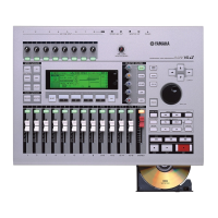
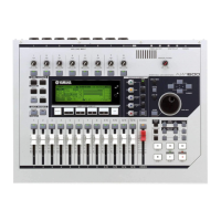
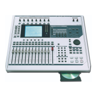
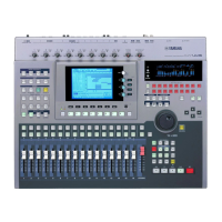
Visual overview of the top panel controls, including navigation, mixer, and sampler sections.
Describes data entry/control section, locate, and transport panel elements.
Details rear panel I/O connectors and front panel CD-RW drive.
Illustrates the placement of components on the main and SUB-AN circuit boards.
Step-by-step instructions for disassembling the unit, from cover removal to board access.
Pinout and function details for various LSI chips including CPU, ADC, and DIR.
Block diagrams for essential ICs like Inverters, Amplifiers, Converters, and Transceivers.
Component layout diagram for the MAIN circuit board.
Component layout diagram for the PN circuit board.
Component layout diagrams for the SUB-AN circuit boards.
Component layout diagram for the SUB-LCD circuit board.
Details inspection procedures, required tools, and test parameters for various sections.
Guide on preparing, starting, selecting, and executing tests in the diagnostic program.
Tests for switches, encoders, faders, LEDs, DSPs, HDD, I/O, CD-RW, Clock, SDRAM.
Comprehensive list of system messages, including general and popup messages, with their explanations.
Comprehensive list of all parts, including overall assemblies and electrical components with part numbers.
High-level block diagram and detailed schematics for the MAIN circuit board.
Circuit diagrams for the PN board, detailing its components and connections.
Circuit diagrams for the SUB-AN board, showing analog and digital signal paths.
Circuit diagram for the SUB-LCD board, illustrating its connections and components.
Circuit diagram for the SUB-IDE board, showing IDE interface connections.
| Type | Digital Audio Workstation |
|---|---|
| Number of Tracks | 16 |
| Simultaneous Recording Tracks | 8 |
| Simultaneous Playback Tracks | 16 |
| Sampling Rate | 44.1 kHz |
| Bit Depth | 24-bit |
| A/D Conversion | 24-bit |
| D/A Conversion | 24-bit |
| Internal Hard Drive | 40GB |
| Outputs | 2 x TRS (L/R), 2 x TRS (Monitor), 1 x Headphone |
| Digital I/O | S/PDIF |
| Tracks | 16 |
| Built-in Effects | Yes |
| Number of Input Channels | 8 |
| Phantom Power | Yes |
| Motorized Faders | No |
| Display | LCD |
| CD-R/RW Drive | Yes |
| Weight | 8.6 lbs |
| Effects | Reverb, Chorus, Delay, Flanger, Phaser, Distortion |
| Inputs | 8 |
| Faders | 8 |
| Storage | 40 GB |