EasyManua.ls Logo

Yamaha AW4416 Service Manual

Yamaha AW4416
154 pages
To Next Page IconTo Next Page
Page #1 background imageLoading...
Page #1 background image
12
11
10
9
8
7
6
5
4
3
2
1
ABCDEFGH I JKLMNOPQ
12
11
10
9
8
7
6
5
4
3
2
1
ABCDEFGH I JKLMNOPQ
AW4416 OVERALL CIRCUIT DIAGRAM 1/6 (MAIN1/4)
AW4416 AW4416
AW4416
MAIN
1/4
OP AMP
OP AMP
OP AMP
OP AMP
OP AMP
OP AMP
OP AMP
OP AMP
REGULATOR
-5V 0.5A
REGULATOR
-5V 0.5A
OP AMP
OP AMP
OP AMP
OP AMP
OP AMP
OP AMP
OP AMP
OP AMP
ADC/DAC
OP AMP
OP AMP
OP AMP
OP AMP
OP AMP
OP AMP
OP AMP
OP AMP
OP AMP
OP AMP
OP AMP
ADC/DAC
ADC/DAC
ADC/DAC
Note : See parts list for details of circuit board
component parts
: Ceramic Capacitor
: Metal Film Resistor
: Metal Oxide Film Resistor
1
LINE/MIC
2
LINE/MIC
3
LINE/MIC
PEAK
PEAK
PEAK
PEAK
PEAK
PEAK
PEAK
PEAK
30K
30K
4
LINE/MIC
30K
30K
5
LINE/MIC
30K
30K
6
LINE/MIC
30K
30K
7
LINE/MIC
30K
30K
8
LINE/MIC
30K
30K
30K
30K
30K
30K
PHONES
MIN/MAX
MONITOR OUT
MIN/MAX
16
: Not installed
NJM79M05FA(XE436A00)
REGULATOR -5V
1
2
3
1: OUTPUT
2: INPUT
3: COMMON
µPC2933T(XS516A00)
REGULATOR +3.3V
1: V in
2: GND
3: V out
1
2
3
NJM78M05DLA(XS534A00)
REGULATOR +5V
1: INPUT
2: GND
3: OUTPUT
1
2
3
NJM7808DLA(XY628A00)
REGULATOR +8V
1: INPUT
2: GND
3: OUTPUT
1
2
3
NJM7810DLA(XW617A00)
REGULATOR +10V
1: INPUT
2: GND
3: OUTPUT
1
2
3
KEC-92554
MAIN (HA)
MAIN (AD / DA)
KEC-92554
9
INSERT I/O
BAL
BAL
BAL
ON
1
2
OFF
PHANTOM +48V
INSERT I/O
BAL
BAL
3
4
5
6
7
8
BAL
Hi - Z
39K
39K
to MAIN4/4 (D-2)
to MAIN3/4 (P-11)
to MAIN3/4 (B-11)
to MAIN3/4 (P-11)
to SUB-CPU - CN201
to MAIN4/4 (G-5)
to Power
Supply Unit

Other manuals for Yamaha AW4416

Question and Answer IconNeed help?

Do you have a question about the Yamaha AW4416 and is the answer not in the manual?

Yamaha AW4416 Specifications

General IconGeneral
TypeDigital Audio Workstation
Mixer Channels44
Sampling Frequency44.1 kHz
Bit Depth24-bit
A/D Conversion24-bit
D/A Conversion24-bit
EffectsYes
Digital I/OADAT, S/PDIF
MIDIIn/Out/Thru
Built-in CD-RW DriveYes
Tracks16
Simultaneous Recording Tracks8
Simultaneous Playback Tracks16
EQ4-band parametric
StorageInternal hard drive
DisplayLCD display
Inputs8 XLR/TRS combo inputs
Faders17 x 100mm motorized faders

Summary

AW4416 Overall Circuit Diagrams

AW4416 OVERALL CIRCUIT DIAGRAM 1/6 (MAIN1/4)

Overall circuit diagram for the AW4416, part 1 of 6 (MAIN).

AW4416 OVERALL CIRCUIT DIAGRAM 2/6 (MAIN2/4)

Overall circuit diagram for the AW4416, part 2 of 6 (MAIN).

AW4416 OVERALL CIRCUIT DIAGRAM 5/6 (PN-SW, PN-INV)

Overall circuit diagram for the AW4416, part 5 of 6 (PN-SW, PN-INV).

AW4416 OVERALL CIRCUIT DIAGRAM 6/6 (SUB-FADER, SUB-CPU, PN-ENC)

Overall circuit diagram for the AW4416, part 6 of 6 (SUB-FADER, SUB-CPU, PN-ENC).

Parts List

Overall Assembly Diagram

Bottom Chassis Assembly Diagram

Circuit Board Layout (Bottom View)

Disassembly Procedure

Hard Disk Installation

Optional Drive Installation

I/O Card Installation

General Specifications

Mixer Section Input/Output

Controls Overview

Mixer and Layer Controls

Mixer Section Controls

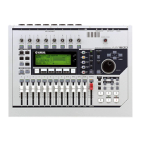
Details of MIXER section controls like VIEW, PAN, EQ, DYN.

Fader Mode Section

Overview of FADER MODE buttons for AUX and EFF.

Mixing Layer Section

Explanation of MIXING LAYER controls for input and monitor.

Recorder and Automation Controls

Recorder Section

Explanation of RECORDER section controls like TRACK and EDIT.

Navigation and Locate Controls

Transport and Sampling Controls

Hard Disk Installation Procedure

Optional Drive Installation Procedure

CD-RW Drive Installation

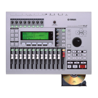
Steps for installing a CD-RW drive, including SCSI ID settings.

I/O Card Installation Procedure

Test Program Overview

MIDI Data Format

MIDI Message Formats

Block Diagram - Analog Section

Block Diagram - Main CPU Section

Block Diagram - DSP Section

Block Diagram - Recorder CPU Section

Block Diagram - Sub CPU Section

Related product manuals