EasyManua.ls Logo

Yamaha CP33 Service Manual

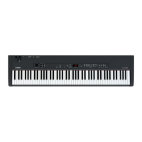
Yamaha CP33
81 pages
To Next Page IconTo Next Page
Page #1 background imageLoading...
Page #1 background image
SERVICE MANUAL
Copyright (c) Yamaha Corporation. All rights reserved. PDF
MI
’06.05
SY
011825
CONTENTS(目次)
SPECIFICATIONS(総合仕様)................................................... 3
PANEL LAYOUT(パネルレイアウト)...................................... 4
DISASSEMBLY PROCEDURE(分解手順)............................... 7
LSI PIN DESCRIPTION(LSI端子機能表)............................... 13
IC BLOCK DIAGRAM(ICブロック図).................................... 16
CIRCUIT BOARDS(シート基板図)........................................ 16
TEST PROGRAM(テストプログラム).............................. 26/33
BULK DUMP(BACKING UP THE DATA)
(バルクダンプ(データのバックアップ)........................ 40/43
FACTORY PRESET RECALL(初期設定に戻すには)......... 46/48
MESSAGE LIST(メッセージ一覧)......................................... 50
SYSTEM BOOTING FLOWCHART
(起動フローチャート)..................................................... 51/52
MIDI IMPLEMENTATION CHART (VOICE) ........................... 53
MIDI IMPLEMENTATION CHART (MASTER)....................... 54
MIDI DATA FORMAT ............................................................. 55
PARTS LIST
BLOCK DIAGRAM(ブロックダイアグラム)
CIRCUIT BOARD LAYOUT & WIRING
(ユニットレイアウト&結線図)
OVERALL CIRCUIT DIAGRAM(総回路図)
20060525-147000

Table of Contents

Question and Answer IconNeed help?

Do you have a question about the Yamaha CP33 and is the answer not in the manual?

Yamaha CP33 Specifications

General IconGeneral
TypeStage Piano
Number of Keys88
Polyphony64
Voices14
EffectsReverb, Chorus
Key ActionGraded Hammer
Sound EngineAWM (Advanced Wave Memory)
EQ3-band
ConnectivityMIDI In/Out, Sustain Pedal

Summary

SPECIFICATIONS

PANEL LAYOUT

Front Panel Controls

Overview of controls and indicators on the front of the unit.

Rear Panel Connectors

Overview of connectors and ports on the rear of the unit.

DISASSEMBLY PROCEDURE

Upper Case Assembly

Procedure for removing the top cover assembly.

Circuit Boards & Assemblies

Steps for removing various circuit boards and assemblies.

Keyboard Assembly

Procedure for removing the keyboard assembly from the unit.

Side Cover Assembly (L, R)

Instructions for removing the left and right side covers.

Front Rail Assembly

Steps for removing the front rail assembly.

Disassembling the Keyboard Assembly

Detailed steps for disassembling the keyboard assembly.

LSI PIN DESCRIPTION

ISP1161A1BD USB Controller

Pin configuration and functions for the USB controller IC.

AK4385ET DAC

Pin configuration and functions for the DAC IC.

YMW767-VTZ CPU

Pin configuration and functions for the CPU IC.

HD6433690B70FYV CPU

Pin configuration and functions for the CPU IC.

μPD780031AYGK LKS / E-PNS2a

Pin configurations for LKS and E-PNS2a ICs.

IC BLOCK DIAGRAM

CIRCUIT BOARDS

AJACK Circuit Board

Component layout and wiring diagram for the AJACK board.

DJACK Circuit Board

Component layout and wiring diagram for the DJACK board.

MVR Circuit Board

Component layout and wiring diagram for the MVR board.

PNL Circuit Board

Component layout and wiring diagram for the PNL board.

PNR Circuit Board

Component layout and wiring diagram for the PNR board.

SVR Circuit Board

Component layout and wiring diagram for the SVR board.

MK SUB Circuit Board

Component layout and wiring diagram for the MK SUB board.

GHD EBUS L Circuit Board

Component layout and wiring diagram for the GHD EBUS L board.

GHD M Circuit Board

Component layout and wiring diagram for the GHD M board.

GHD H Circuit Board

Component layout and wiring diagram for the GHD H board.

TEST PROGRAM

Test Program Preparation

Required instruments, settings, and connections for testing.

Entering Test Program

Methods to access the product's test mode.

Test Program Execution

Steps for executing tests, interpreting results, and navigating.

Test Items Overview

Detailed list of tests, functions, and judgment criteria.

MIDI Code Test Program

Using MIDI codes to select and execute test items.

BULK DUMP (BACKING UP THE DATA)

FACTORY PRESET RECALL

Function Settings

Details on adjustable functions and their default values.

Master Mode Settings

Settings specific to master mode operations.

MESSAGE LIST

SYSTEM BOOTING FLOWCHART

MIDI IMPLEMENTATION CHART (VOICE)

MIDI IMPLEMENTATION CHART (MASTER)

MIDI DATA FORMAT

Note On/Off & Control Change Formats

Data formats for note and control change MIDI messages.

Mode & Program Change Formats

Data formats for mode and program change messages.

System Exclusive Message Formats

Data formats for system exclusive MIDI messages.

PARTS LIST

OVERALL ASSEMBLY

UPPER CASE ASSEMBLY

PEDAL ASSEMBLY

KEYBOARD ASSEMBLY (GHD-EBUS鍵盤)

ELECTRICAL PARTS

CP33 BLOCK DIAGRAM

CP33 CIRCUIT BOARD LAYOUT & WIRING

CP33 OVERALL CIRCUIT DIAGRAM 1/2

CP33 OVERALL CIRCUIT DIAGRAM 2/2

Related product manuals