CP33
9
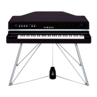
Fig. 4(図4)
4. Side Cover Assembly (L, R)
(Time required: About 4 minutes)
4-1 Remove the upper case assembly. (See procedure 1)
4-2 Remove the five (5) screws marked [270D]. The side
cover assembly R can then be removed. (Fig. 4)
* The side cover assembly L can then be removed in
the same manner.
4.
腕木Assy(L・R)
(所要時間:約 4 分 )
4-1 上ケースAssyを外します。(1項参照)
4-2 [270D]のネジ5本を外し、腕木Assy(R)を外します。
(図4)
※ 腕木Assy(L)も同様に外すことができます。
5. Front Rail Assembly
(Time required: About 6 minutes)
5-1 Remove the upper case assembly. (See procedure 1)
5-2 Remove the keyboard assembly. (See procedure 3)
5-3 Remove the seven (7) screws marked [120] located
under the keybed. (Fig. 1)
5-4 Remove the four (4) screws marked [140]. Move the
front rail assembly forward, and it can then be removed.
(Fig. 5)
* When mounting the front rail assembly, always start
by tightening screws
q
,
w
in sequence. (Fig. 1)
5. 口金Assy(所要時間:約 6 分 )
5-1 上ケースAssyを外します。(1項参照)
5-2 GHDEBUS鍵盤を外します。(3項参照)
5-3 棚板下側より[120]のネジ7本を外します。(図1)
5-4 [140]のネジ4本を外し、口金Assyを前方にスライド
させて外します。(図5)
※ 口金Assyを取り付ける際、まず最初にq、wのネジを順に
締めます。(図1)
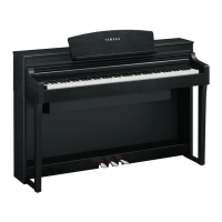
Fig. 5(図5)
[140]: BindHeadTappingScrew-B(Bタイト+BIND)3.0X6
MFZN2W3(WE936300)
[270D]: BindHeadTappingScrew-B(Bタイト+BIND)3.0X6
MFZN2W3(WE936300)
Side cover R
(腕木R)
[270D]
[270D]
[140]
[140]
Front rail assembly(口金Ass'y)
Keybed(棚板)
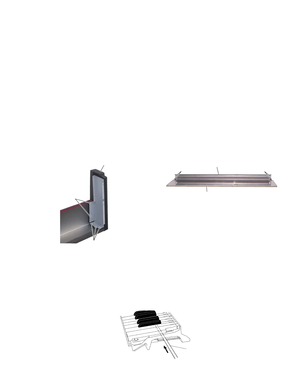
6. Disassembling the Keyboard Assembly
* After inserting a round stick (Rod: TX000670) between
the frame and the keys, remove the circuit boards.
(Fig. 6)
Round stick (丸棒)
(Rod: TX000670)
Fig. 6 (図6)
6. GHDEBUS鍵盤の分解
※ シートをはずす前に、接点ゴムを歪ませないように、フ
レームとハンマーの間に丸棒(ロッド:TX000670)を挿入
しておきます。(図6)
 Loading...