Do you have a question about the Yamaha CT-7000 and is the answer not in the manual?
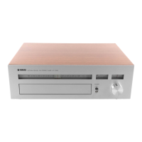
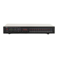
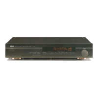
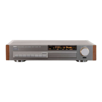
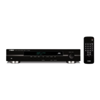
Details components and controls on the front of the tuner unit.
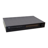
Identifies connections and ports on the rear for North American models.
Identifies connections and ports on the rear for European models.
Illustrates and labels components visible from the top inside the unit.
Illustrates and labels components visible from the bottom inside the unit.
Explains the function and operation of the signal and multipath meter circuit.
Describes the circuit that automatically adjusts stereo blend based on signal strength.
Explains the circuit that temporarily disables AFC during tuning and indicates station lock.
Details the circuit designed to cancel noise from power switch operation.
Explains the circuit that eliminates weak signals and inter-station noise during tuning.
Describes the PLL circuit for creating a switching signal and stereo component separation.
Details the circuit that drives the stereo/mono modes and stereo indicator lamp.
Explains the switching method to separate left and right audio signals from the composite signal.
Details various tests and adjustments for the tuner section of the device.
Specifies adjustments and required instruments for the RF Pack.
Outlines overall adjustment procedures for the IF Circuit Board.
Details overall adjustment procedures for the Discriminator circuit board.
Lists adjustments for VCO, Separation, and Output Level on the MPX Board.
Specifies adjustments for Separation and Signal Meter on the Control Board.
Identifies VCO adjustment for the Power Circuit Board.
Shows the electrical connections between various circuit boards and components.
Provides the schematic layout and component identification for the IF circuit board.
Presents the schematic layout and component identification for the Discriminator circuit board.
Displays the schematic layout and component identification for the MPX circuit board.
Shows the schematic layout and component identification for the Volume circuit board.
Displays the schematic layout and component identification for the Meter Lamp circuit board.
Presents the schematic layout and component identification for the Lamp circuit board.
Details power supply variations for U.S./Canadian and European models.
Illustrates antenna connection differences for the European model.
Lists and illustrates components visible on the front panel of the unit.
Lists and illustrates components visible inside the unit from the top.
Lists and illustrates additional internal components of the unit.
Shows an exploded view with numbered components for assembly reference.
| Tuning Bands | FM, MW |
|---|---|
| Tuning Scale | Analog |
| FM Tuning Range | 88 to 108 MHz |
| Signal to Noise Ratio (AM/MW) | 50 dB |
| Selectivity (FM) | 80 dB |
| MW Tuning Range | 530 to 1600 kHz |
| AM Tuning Range | 530 - 1605 kHz |
| Frequency Response (FM) | 30Hz to 15kHz |
| Sensitivity (AM/MW) | 30 µV |