EasyManua.ls Logo

Yamaha TX-550 Service Manual

Yamaha TX-550
25 pages
To Next Page IconTo Next Page
Page #1 background imageLoading...
Page #1 background image
AM/FM
STEREO
TUNER
TX-550
SERVICE MANUAL
FRONT PANEL
CONTENTS
TO
SERVICE
PERSONEL
1
INTERNAL
VIEW
1
REAR
PANELS
2
SPECIFICATIONS
3
DIMENSIONS
3
DISASSEMBLY
PROCEDURES
3
ADJUSTMENTS
4~9
DISPLAY
PIN
CONNECTIONS
10
fi-COM
DATA
-
11
BLOCK DIAGRAM
12
WIRING
13
PRINTED
CIRCUIT BOARD
-.14,15
SCHEMATIC
DIAGRAM
16
PARTS LIST
17-21
YAMAHA
YAMAHA CORPORATION
P.O.
Box
1
.Hamamati^.Japan
3.25K-842
Q
®
Printed
in
Japin
’91.8

Other manuals for Yamaha TX-550

Question and Answer IconNeed help?

Do you have a question about the Yamaha TX-550 and is the answer not in the manual?

Yamaha TX-550 Specifications

General IconGeneral
BrandYamaha
ModelTX-550
CategoryTuner
LanguageEnglish

Summary

Service Personnel Guidelines

Internal Component Layout

Diagram showing the placement of internal components and their identification numbers.

Rear Panel Connections

Technical Specifications

Unit Dimensions

Detailed measurements of the tuner unit in millimeters and inches.

Disassembly Instructions

Step-by-step guide for safely disassembling the tuner unit.

Tuner Calibration and Adjustments

Pre-Adjustment Setup

Initial steps and conditions required before performing calibration adjustments.

Measurement Instrument Glossary

List of abbreviations for test equipment used in the adjustment procedures.

Preset Memory Confirmation

LCD Display Confirmation

Procedure to verify the correct display output and modes on the LCD unit.

AM Tuner Calibration

Digital Control System

Memory Preset Operation

Instructions for storing and recalling radio station presets using the digital controls.

Tuning Mode Selection

Explanation of different tuning modes available on the digital control system.

Digital Control Features and Checks

Tuning Lock Feature Check

Procedure to verify the functionality of the tuning lock feature.

Last Station Recall Function

Verification of the unit's ability to recall the last tuned station.

Remote Control Operation Verification

Confirming the proper functioning of the remote control for station selection.

Display Pinout and Connections

Microcomputer Data (µ-COM)

Internal Wiring Diagrams

System Block Diagram

Printed Circuit Board Layout

Schematic Circuit Diagram

Component Parts List

Electrical Component Details

List of electrical components, including part numbers and specifications.

Mechanical Component List

Exploded View of Unit

Included Accessories

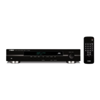
List and identification of accessories provided with the tuner unit.

Related product manuals