Do you have a question about the Yamaha Disklavier DKC55RCD XG Mark III and is the answer not in the manual?
Details on the laser diode's material and wavelength for safe servicing.
Details on sensor, drive, data storage, and removable media.
Specifications for control unit, amplification, and connectors.
Details on pitch, silent system, SmartKey, and accessories.
Covers playback functions, controls, and recording features.
Includes silent system, metronome, editing, and utility controls.
Basic structural details for specific Disklavier full-function models.
Basic structural details for other Disklavier full-function models.
New features related to the CD-ROM drive in full-function models.
Information on expanded memory and programs for all models.
Details on the SmartKey system exclusive to full-function models.
Instructions on how to play the SmartKey demonstration.
Diagram of the C3 type unit's bottom view layout.
Diagram of the C3 type unit's side view layout.
Diagram of the C1 type unit's bottom view layout.
Diagram of the C2 type unit's bottom view layout.
Diagram of the C5 type unit's bottom view layout.
Diagram of the C6 and C7 types' bottom view layout.
Diagram of the GA1 and A1 types' bottom view layout.
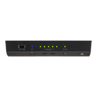
Diagram of the control unit's front panel components.
Diagram of the control unit's rear panel connectors.
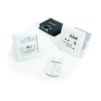
Diagram of the switch box controls and jacks.
Diagram of the remote controller buttons.
Diagram of the amplifier unit's front panel ports and controls.
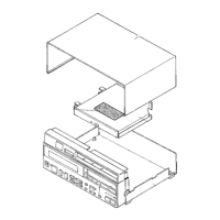
Disassembly steps for control unit, top cover, CD-ROM, DA, DSP, panel, and CDPAN.
Disassembly steps for panel unit CD, PASW, LCD, FDD, controller, and speaker.
Disassembly steps for MA120 assembly/board, PWB, FU, MD-GP, and PK-CTL boards.
Instructions for removing the action unit and hammer sensor unit.
Disassembly of key sensor circuit board, unit, and coil assembly.
Instructions for removing the MD-GP unit and its circuit board.
Step-by-step instructions for removing the pedal drive unit.
Disassembly of PK-CTL, DRIVE A/B/C, MA120, and NW circuit boards/units.
Disassembly steps for the MA120 assembly/board and PWB board.
Disassembly procedures for FU, Power Transformer, Speakers, NW, and HP boards.
Diagrams for JACK, PWB, MN, DRIVE A, B, and C circuit boards.
Diagrams for sensor, control, DSP, MA120, PASW, PK-CTL, HP, FU, MD-GP boards.
Procedures for testing patterns, adjusting tone, and measuring pedals.
Covers pedal maintenance, auxiliary modes, keyboard measurement, and EEP-ROM.
Tests for DSP, RAM, FLASH, AI2, Digital I/O, CTRL, CD, and Test Tone.
Tests for SEMG, key/hammer sensors, pedals, and other specific functions.
Checking unit version and performing basic hardware tests.
Tests for host, MIDI, floppy drive, and calendar interfaces.
Pass numbers for pedal and keyboard conditions with countermeasures.
Conditions used when pass numbers have occurred in playback.
List of error messages and descriptions for the controller board.
Guides for power, control unit, remote, playback, metronome, pedal, and tone generator issues.
Troubleshooting MIDI connection, disk utilities, and general errors.
Block diagrams for control unit, DSP, CD PAN, DA, drives, sensors, and more.
Wiring schematics for switch box, amplifier, FU, PWB, drives, MD-GP, and control units.
| Model | DKC55RCD XG Mark III |
|---|---|
| Type | Control Unit |
| Category | Control Unit |
| Manufacturer | Yamaha |
| MIDI | Yes |
| XG | Yes |
| Display | LCD |
| Storage | Floppy Disk Drive |
| CD Player | Yes |
| Functions | MIDI Control |
| Connectivity | MIDI In/Out |