10
MD Unit
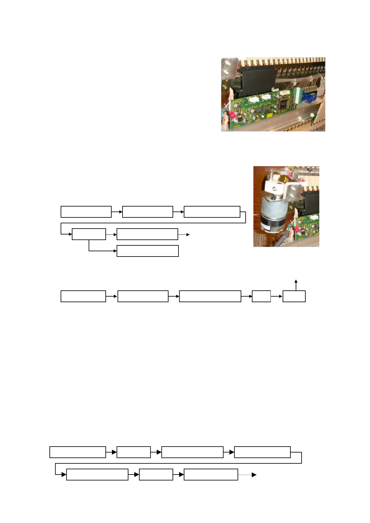
4-5. Hammer Sensor Unit Upright Piano Hammer Sensor Unit
The hammer sensor consists of the hammer
sensor sheet, optic fiber, light source/receiver.
Hammer movement causes the metal shutter
attached to the hammer shank of each key to
break the LED light beam as it passes from the
optic fiber to the sensor head.
5. MD Unit
When the silent pedal (GP: quiet switch) is operated,
the MD unit receives the driving data of the shank
stopper as below rout.
■MD driving data flow
Upright Piano
Grand Piano
6. PS (Power) Unit
The power unit supplies each unit with its required power.
The power cord for the powered speaker can be connected to the AC outlet. On the E3
power unit, protection circuits operate and shut down the power when excessive
current is detected in the drive, however in the PS unit, which was described in drive
unit section, individual poly switches function when excessive current is detected so
electric current is not switched off.
+48V Power for drive circuits
+12V Supplies each unit with power, and converts power within unit.
+5V For standby circuit
In quiet mode, the switch box outputs the piano sound to headphones as below.
Headphones
Silent Pedal(SW) Pedal Drive Board
Key Drive Board
CSPBoard
MDUnit
Control Unit
Shank Stopper
Quiet switch
PS unit(D-SUB)
CSP
MD Control unit
Switch BOX
Key sensor board CSP board
Control unit PS(Digital Audio)
Control Unit PS(D/A) Switch BOX
8
Shank Stopper