Do you have a question about the Yamaha DME Series and is the answer not in the manual?
Install the DME Designer application and the DME-N Network Driver.
Install the driver for connecting a DME unit using a USB cable.
Connect a single DME unit to a computer using a USB cable for basic configuration.
Configure settings for expansion cards when used with DME units.
Add and connect components within the DME Designer configuration area.
Setup at least one scene for the created data before going online.
Establish connection between DME Designer and the DME unit via synchronization.
Verify sound output by configuring HA control and checking input levels.
Connect multiple DME units to a computer using Ethernet cables.
Assign IP addresses to DME units for network connection.
Configure the computer's IP address settings for network communication.
Connect DME units and the computer to a network switch.
Configure the DME-N Network Driver for communication.
Establish connection and synchronization between DME units and DME Designer.
Connect optional external controllers like ICP1, CP4SF for remote control.
Configure device group and IP settings directly from DME64N/24N front panels.
Configure device information for communication using the DME-N Network Driver window.
Configure automatic detection and setup files for the DME-N Network Driver.
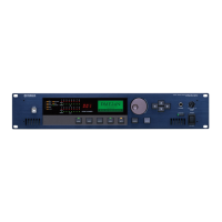
This manual describes the process of setting up a DME system, from making the initial DME unit settings (DME64N / DME24N / DME8i-C / DME80-C / DME4io-C / DME8i-ES /DME80-ES / DME4io-ES) to synchronizing the DME Designer application installed on a computer.
The DME Setup Manual serves as a comprehensive guide for users to effectively install, configure, and maintain their DME (Digital Mixing Engine) units and associated software. It covers a range of topics from initial software installation to advanced network setups and troubleshooting, ensuring a smooth user experience.
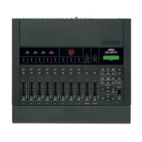
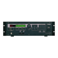
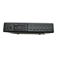
The DME system is designed for advanced audio processing and system control, offering robust solutions for various professional audio environments. At its core, the system comprises DME units (DME64N, DME24N, DME8i-C, DME80-C, DME4io-C, DME8i-ES, DME80-ES, and DME4io-ES) and the DME Designer application.
The DME Designer application is a dedicated software used for making system settings within DME units and for conveniently setting up sound-processing configurations. This application allows users to design and implement complex audio routing, processing, and control schemes. It can be used independently on a computer, even without a connected DME unit, for offline design and preparation.
DME units are the hardware components that execute the audio processing and control logic designed in the DME Designer. These units can be connected to a computer either via a USB cable for basic, single-unit setups or via Ethernet cables for more advanced, multi-unit network configurations. The choice of connection method depends on the complexity and scale of the audio system.
The system supports various expansion cards (e.g., MY4-AD, MY4-DA, MY8-AD, MY8-AD24, MY8-AD96, MY8-ADDA96, MY8-AE, MY8-AE96, MY8-AE96S, MY8-AT) that extend the I/O capabilities and processing power of the DME units. These cards are configured within the DME Designer, allowing for tailored hardware integration.
Scene management is a key feature, enabling users to save and recall different configurations and settings. This is crucial for live sound applications or installations where various presets need to be quickly accessed. The system also includes a "Go On-line" function, which synchronizes the settings from the DME Designer to the connected DME units, ensuring that the hardware operates according to the designed configuration.
For external control, the DME system integrates with optional extras such as ICP1, CP4SF, CP1SF, and CP4SW controllers. These controllers provide remote access to various parameters, either via Ethernet for intelligent control panels or via General Purpose Interface (GPI) for simpler control panels.
The setup begins with downloading the DME Designer Combo Installer and the USB-MIDI Driver from the Yamaha Pro Audio website. The Combo Installer includes both the DME Designer application and the DME-N Network Driver, which is essential for Ethernet connections. The USB-MIDI Driver is required for USB connections. The installation process is guided by a setup wizard, ensuring all necessary components are correctly installed.
For basic setups, a single DME unit can be connected directly to a computer via a USB cable. Before launching DME Designer, the DME unit must be powered on and connected. Once connected, the DME Designer will display two windows: the Main Panel window and the Designer window. Users can then double-click the DME icon or drag and drop it into the editing area to configure the unit. This includes setting up expansion cards, configuring components (like Analog Input, EQ, Fader, Delay-Short), and connecting them visually within the Designer window.
After configuring components, at least one scene must be set up. This involves using the Scene Manager to store the current configuration. The "Go On-line" function synchronizes the Designer's settings with the DME unit. During synchronization, the system may mute audio, and users are prompted to save the Designer file. Once online, the DME unit operates according to the loaded configuration, and sound output can be checked, including configuring head amp control for models with this feature.
For more complex systems involving multiple DME units, long cable runs, or wireless connections, Ethernet cables are used. This requires assigning unique IP addresses to each DME unit and the computer. The manual details how to set up a "Device Group" with a "Group Master" and "slaves," and how to configure network settings (Master/Slave status, IP Address, Link Mode) for each unit using DME Designer via a temporary USB connection. The DME-N Network Driver settings on the computer also need to be configured to recognize the networked DME units.
DME64N and DME24N units allow for direct configuration of device group and IP address settings via their front panels. This is useful for initial setup or adjustments without a computer. Users can navigate through utility menus to set parameters like Master/Slave status, IP Address, Master ID, and Link Mode.
Once network settings are established, DME Designer is launched, and connected devices are placed in the configuration. The Port dialog box is used to ensure correct Tx/Rx and Device Group settings. The "Go On-line" function then synchronizes the entire networked system, displaying all device IP addresses and allowing selection of the master device for synchronization.
The manual provides an extensive troubleshooting section covering common issues such as:
The manual implicitly emphasizes maintenance through regular updates. It directs users to the Yamaha Pro Audio website for the latest versions of the DME Designer Combo Installer, USB-MIDI Driver, and DME unit firmware. Keeping software and firmware up-to-date ensures compatibility, stability, and access to new features or bug fixes.
The "Automatic backup function and going online" feature is a critical maintenance aspect. When synchronizing with DME Designer version 3 or later, the system can create a backup of the computer's current data (.daf) within the DME unit's memory. This safeguards against accidental deletion or loss of the original project file, ensuring that synchronization can still occur even if the local file is lost. Users are advised to use the "Store Project File into DME after synchronization" option or the "DME File Storage" item from the [File] menu to store a copy of the project file on the DME device(s).
The "Analyze function" in DME Designer is a vital tool for system maintenance and optimization. After creating a configuration, using this function helps determine the viability of the design and ensures that DSP total resource consumption does not exceed the upper limit. This proactive check prevents compile errors during synchronization and ensures stable operation. If resource consumption is too high, users are advised to delete unneeded components, replace components with less resource-intensive alternatives, or divide the processing load.
The detailed DME-N Network Driver settings provide granular control over how the computer communicates with DME units. This includes managing the "Target Device List" (adding, duplicating, removing units), configuring "Device Information" (Name, IP Address, MAC Address, Port No.), and using "Advanced Settings" for automatic detection of units. These features allow for precise control and troubleshooting of network communication, ensuring reliable system operation. The ability to import and export setup files for the DME-N Network Driver also facilitates easy migration or backup of network configurations.
Recommendations on cable types and lengths (e.g., Cat 5 shielded twisted-pair cables for Ethernet, CPEV cables for GPI) are provided to maximize resistance to electromagnetic interference and ensure reliable connections over specified distances.
The comprehensive troubleshooting chart serves as a quick reference for diagnosing and resolving operational issues. This empowers users to identify possible causes and corrective actions, minimizing downtime and ensuring continuous operation of the DME units.
By following the guidelines and utilizing the features described in the DME Setup Manual, users can effectively install, configure, and maintain their DME systems for optimal performance in professional audio applications.
| Manufacturer | Yamaha |
|---|---|
| Model Series | DME Series |
| Software Control | DME Designer |
| Sampling Frequency Rate | 48 kHz |
| Internal Processing | 32-bit |
| Total Harmonic Distortion | 0.005% |
| Frequency Response | 20 Hz - 20 kHz |
| Connectivity | Ethernet, MIDI, Analog, Digital |
| Control | Ethernet |
| Input Channels | Varies by model |
| Output Channels | Varies by model |
| Network Capability | Ethernet for control and monitoring |
| Compatibility | Windows |
| Type | Digital Mixing Engine |