EasyManuals Logo

Yamaha DSP-1 User Manual

Yamaha DSP-1
40 pages
To Next Page IconTo Next Page
To Previous Page IconTo Previous Page
Page #14 background imageLoading...
Page #14 background image
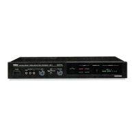
E
FRONT
PANEL
@
POWER
switch
Turn
the
power
on
and
off.
When
the
power
is
turned
on,
the
last
program
before
the
power
has
been
turned
off
is
automatically
recalled
“For
several
seconds
after
the
power
is
turned
on,
the
sound
is
muted
by
the
protection
circuit.
®
MIX
INPUT
jacks
(MONO,
L,
R)
Used
to
mix
the
sound
signal
with
the
input
source
from
the
INF'UT
jacks
on
the
rear
panel.
Use
MONO
when
the
output
terminal
of
the
equipment
to
be
connected
is
monaural,
and
connect
L
and
R
jacks
when
the
equipment
is
stereo.
If
both
the
MONO
and
L/R
jacks
are
used
simultaneously,
the
level
from
the
MONO
jacks
may
be
lowered.
@
MIX
INPUT
LEVEL
control
Used
to
adjust
the
input
level
from
the
MIX
INPUT
jacks.
Turning
it
clockwise
increase
the
input
signal
level.
@
TAPE
selector
7
Selects
the
input
source
or
the
signal
recording
playback
with
the
tape
deck
connected
to
this
unit.
According
to
the
knob
position,
the
signal
path
changes
as
follows:
è
NORM:
Sound
field
effect
or
special
sound
effect
can
be
applied
to
the
input
source
from
the
rear
panel
INPUT
jacks
or
the
front
pane!
MIX
INPUT
jacks.
|
13
Input
jacks
INPUT
eS)
FRONT
—4
MIX
INPUT
Digital
signai
PROCESSING
processing
circuil
|
|
p>
CY
REAR
TAPE
PB
REC
OUT
Output
jacks
MAIN/“MONO
|
Signal
path
in
the
DSP-1
|
®
MONITOR:
Sound
field
effect
or
special
sound
effect
can
be
applied
to
the
signal
from
the
tape
deck
connected
to
this unit
Signal
path
in
the
DSP-1
Output
jacks
INPUT
MAIN/MONO
;
FRONT—4
MIX
INPUT
Es
dere
chao
PROCESSING
pi
g
REAR
TAPE
;
TAPE
PB
REC
OUT
è
EFFECT
REC:
The
effected
sound
(that
the
sound
field
effect
or
special
sound
effect
is
applied
to
the
input
source
from
the
INPUT
or
M!X
INPUT
jacks)
can
be
recorded
onto
the
tape
deck.
This
signal
is
output
only
from
the
REC
OUT
jacks.
Input jacks
Signal
path
in
the
DSP-1
INPUT
a
Digita)
signai
A
processing
circuit
a
+
Output
Jacks
MAIN/MONO
©
FRONT
MIX
INPUT
PROCESSING
EAR
——!
TAPE
PB
REC
OUT
@
TAPE
PB
LEVEL
control
Used
to
adjust
the
tape
sound
level
input
from
the
TAPE
PB
jacks
on
the
rear
panel.
-
@
Remote
sensor
Receives
the
remote
control
infrared
signal
from
the
remote
control
tramsmitter.
@
MUTE
indicators
(MAIN,
EFFECT)
Lights
when
the
MUTE
key
on
the
remote
control
transmitter
is
pressed
to
mute
the
sound.
®
MAIN:
Lights
when
the
MAIN
MUTE
key
is
pressed
to
mute
the
source
sound.
@
EFFECT:
Lights
when
the
EFFECT
MUTE
key
is
pressed
to
mute
the
effect
sound.
@
MODE
indicators
These
show
the
current
mode;
ACOUSTIC,
SURROUND,
EFFECTOR
or
USER
PROG
mode.
©
PROGRAM
NO.
display
Displays
the
selected
program
number.
@
PROGRAM
display
Displays
the
selected
program
name,
parameter,
etc.
*
The
display
panel
may
not
be
understandable
when
viewed
from
the
certain
direction.
See
it
from
the
front
when
operating.
|

Questions and Answers:

Question and Answer IconNeed help?

Do you have a question about the Yamaha DSP-1 and is the answer not in the manual?

Yamaha DSP-1 Specifications

General IconGeneral
BrandYamaha
ModelDSP-1
CategoryComputer Hardware
LanguageEnglish

Related product manuals