RX-V530/RX-V530RDS/HTR-5550/HTR-5550RDS/DSP-AX530
RX-V430/RX-V430RDS/HTR-5540/HTR-5540RDS/DSP-AX430
21
RX-V530/RX-V530RDS/HTR-5550/HTR-5550RDS/DSP-AX530
RX-V430/RX-V430RDS/HTR-5540/HTR-5540RDS/DSP-AX430
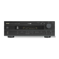
MAIN (10) P.C.B.
MAIN (2) P.C.B.
MAIN (3) P.C.B.
MAIN (1) P.C.B.
MAIN (4) P.C.B.
FUNCTION (5) P.C.B
F
C
B
C
CB253
Fig. 6
RX-V530/RX-V530RDS/HTR-5550/HTR-5550RDS/DSP-
AX530/RX-V430RDS/HTR-5540RDS
RX-V430/HTR-5540/DSP-AX430
F
MAIN (7) P.C.B.
CB253
MAIN (2) P.C.B.
MAIN (3) P.C.B.
MAIN (1) P.C.B.
MAIN (4) P.C.B.
FUNCTION (5) P.C.B
C
B
C
パワートランジスタ、スピーカー保護リレーの交換
手順
BC
Replacement of Power Transistor, Speaker
Protective Relay
It is easy to replace the power transistor and speaker
protective relay of this unit according to the following
procedure.
a. Remove the top cover. (Refer to “1. Top Cover
Removal” on p.18.)
b. Remove 1 screw (B) and 2 screws (C). (Fig. 6)
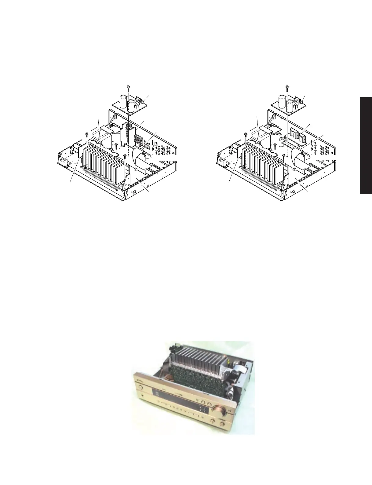
c. Raise the MAIN P.C.B. (Fig. 7)
d. In this state, the power transistor and speaker
protective relay can be replaced. To check the
operation in this state, it is necessary to connect the
grounding cable.
Fig. 7
7. RX-V430/HTR-5540/DSP-AX430:MAIN(10)、
MAIN(2)P.C.B.の外し方
D
E
F
7. RX-V430/HTR-5540/DSP-AX430: Removal of MAIN
(10) and MAIN (2) P.C.B.s
a. Remove 4 screws (D). (Fig. 3)
b. Remove MAIN (10) P.C.B.. (Fig. 6)
c. Remove 1 screw (E). (Fig. 3)
d. Remove 1 screw (F). (Fig. 6)
e. Remove MAIN (2) P.C.B.. (Fig. 6)
 Loading...