EasyManua.ls Logo

Yamaha EMX 2000 - Power Circuit Boards; Power Transformer

Yamaha EMX 2000
69 pages
Print Icon
To Next Page IconTo Next Page
To Previous Page IconTo Previous Page
Loading...
EMX2000
3.
POWER
1/5
Circuit Board
3-1.
Remove
the panel
assembly. (See
procedure
1-1)
3-
2.
Remove
the fifteen
(15)
screws
marked [B60] and the
four
(4)
screws.marked [B50].
Then the
POWER 1/5
circuit board can be
removed.
(Fig.5)
4.
POWER
2/5 Circuit Board
4-
1.
Remove the
panel assembly. (See
procedure
1-1)
4-
2. Remove
the screw
marked [R30A] and the
five
(5)
hexagonal nuts marked
[B]. Then the
POWER 2/5
circuit board
can be removed.
(Fig.
6)
5.
POWER 3/5
Circuit Board
5-
1 .
Remove the panel
assembly. (See procedure
1
-
1
)
5-2.
Remove the
POWER 2/5 circuit
board. (See
procedure
4-2)
5-
3. Remove
the two
(2)
screws marked
[R30B].
Then the
POWER 3/5
circuit board can be
removed. (Fig.
7)
6. POWER 4/5 Circuit
Board
6-
1 . Remove the
panel assembly. (See
procedure 1
-
1
)
6-2.
Remove
the
screw marked
[BllOA].
Then the
POWER 4/5 circuit
board
can be
removed. (Fig.
5)
3.
POWER 1/5
h
3-1.
Panel Ass’y
(1-1
3-
2.
[B60]OT<i/ 15
^
[B50]
(7)
T' v
4
POWER
1/5
1-0
(0
5)
4.
POWER 2/5 *>-
F
4-
1.
Panel Ass’y
S-fX
0
51-
L S
to
(1-1
4-
2.
[R30]cOt'>'lt^i;[B]<7)7’^:ftt
7
^
^
5fl51-
LT.
POWER2/5
V-
h
S-fX“)51-LSto
(0
6)
5.
POWER
3/5
'>-h
5-
1.
Panel Ass’y
1)51- LS
to
5-2.
POWER 2/5
^
®
1) 51-
L S
t
o
(4-2
:®#M)
5-
3.
[R30](7)tv
2tl4r51-L7:,
POWER 3/5
(07)
6.
POWER 4/5
6-
1.
PanelAss’y
^fXl)51-LSto
(l-\
6-2. [B110]Ot
V 1 t:^51-tt,
POWER 4/5
b
^
mALt-fo
(
05
)
7.
POWER 5/5
Circuit
Board
7-1.
Remove the
panel
assembly. (See
procedure
1-1)
7-2.
Remove the
screw
marked [BllOB].
Then
the
POWER 5/5
circuit board
can
be
removed.
(Fig.
5)
8.
POWER
Transformer
8-1.
Remove the
panel
assembly. (See
procedure
1-1)
8-2.
Remove
the
center bolt of the
power
transformer.
Then the
power
transformer can be
removed.
(Fig.
5)
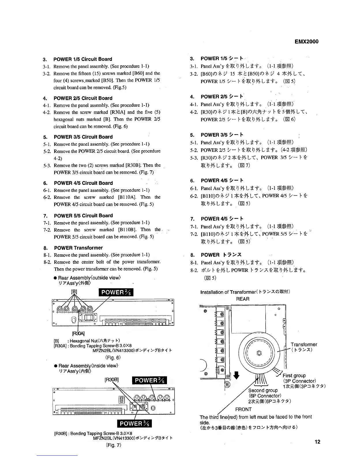
• Rear Assembly(outside
view)
7’Ass'y<i'Mi>
[B] ;
Hexagonal Nut(7\^7-y
b)
[R30A]
: Bonding
Tapping Screw-B
3.0X8
MFZN2BL(VN413300)*'>7-'<>^B^f'f
b
(Fig. 6)
• Rear Assembly(inside
view)
U 7Ass'y<[*3li)
[R30B] : Bonding
Tapping Screw-B
3.0X8
MFZN2BL(VN413300)#>x-f
>yB^^'f
b
(Fig.
7)
7.
POWER
4/5
'>~h
7-1.
Panel Ass’y
1) 51-
L t
to
(1-1
7-
2.
[BllOlOtv
1 :$:S•51L.-C^
POWER5/5 V
-
b
mALt-fo
(
05
)
8.
POWER
8-
1.
Panel Ass’y *lfXl)51-L4to
(1-1
8-2.
b ^51-
L POWER
b y
V)AL
tto
(0
5)
Instaiiation
of Transformer(
bv
VXiT)®!#)
REAR
side.
(ZEA'e>3#icoii®(?!itfe)«7P>
b:^[S]'^isnt5)
12