2-1
GB
000202
i
!0
o
t
y
r
r
u
!1
!1
!2
!3
YAMAHA
q
w
e
!4
!6
!5
!7
x1000 r/min
7
3
4
2
1
5
6
YAMAHA
EMU01206
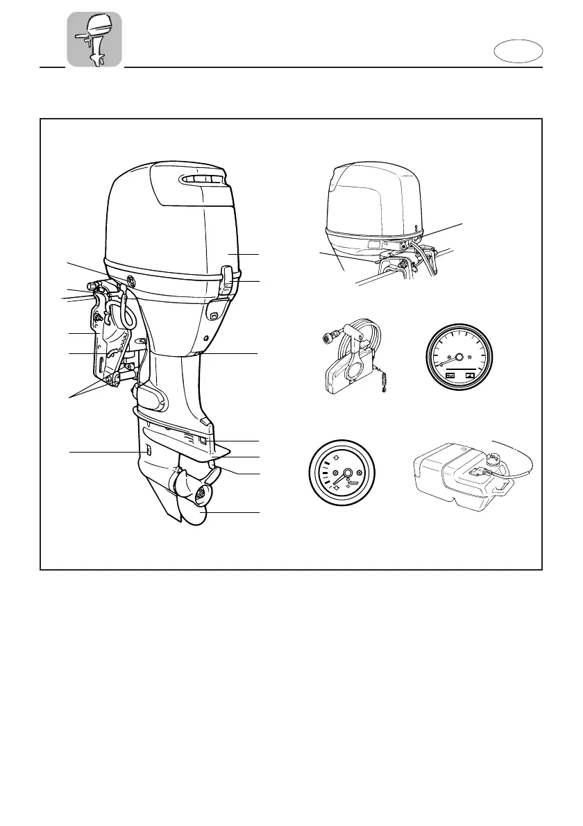
MAIN COMPONENTS
1 Top cowling
2 Cowling lock lever
3 Oil drain bolt
* 4 Anode
5 Anti-cavitation plate
6 Trim tab (anode)
7 Propeller
8 Cooling water inlet
9 Trim angle adjusting-rod
0 Clamp bracket
q Tilt support lever
* w Power trim and tilt switch
* e Warning indicator(s)
r Remote control box (Side mount type)
* t Tachometer
* y Trim meter
u Fuel tank
* May not be exactly as shown; also may not
be included as standard equipment on all
models.
62Y-9-78 (E,F,ES) 2 5/25/00 4:08 PM Page 4