PERIODIC MAINTENANCE AND ADJUSTMENT
6-37
6
4. Install the brake hose holder on
each side by installing the bolt and
nut.
5. Take the vehicle off the center-
stand so that the front wheel is on
the ground.
6. Tighten the wheel axle, the front
wheel axle pinch bolt, and the
brake caliper bolts to the specified
torques.
7. Push down hard on the handlebar
several times to check for proper
fork operation.
EAU44800
Rear wheel (FZ1-S)
WARNING
EWA14840
For the ABS model, have a Yamaha
dealer remove and install the wheel.
EAU40021
To remove the rear wheel
WARNING
EWA10821
To avoid injury, securely support the
vehicle so there is no danger of it
falling over.
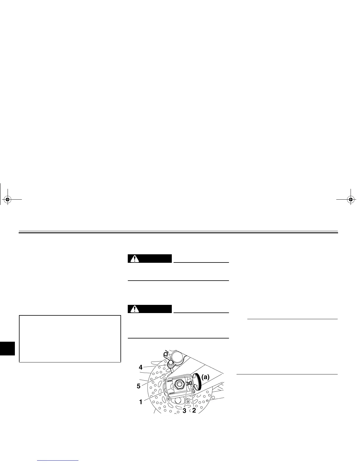
1. Loosen the axle nut.
2. Place the vehicle on the center-
stand.
3. Remove the axle nut.
4. Loosen the locknut on each side of
the swingarm.
5. Turn the drive chain slack adjust-
ing bolts fully in direction (a) and
push the wheel forward.
6. Remove the drive chain from the
rear sprocket.
TIP
● If the drive chain is difficult to re-
move, remove the wheel axle first,
and then lift the wheel upward
enough to remove the drive chain
from the rear sprocket.
● The drive chain cannot be disas-
sembled.
7. While supporting the brake caliper
bracket, pull the wheel axle out,
and then remove the wheel.
NOTICE: Do not apply the brake
after the wheel has been re-
moved together with the brake
disc, otherwise the brake pads
will be forced shut.
[ECA11071]
Tightening torques:
Wheel axle:
72 Nm (7.2 m·kgf, 52 ft·lbf)
Front wheel axle pinch bolt:
23 Nm (2.3 m·kgf, 17 ft·lbf)
Brake caliper bolt:
40 Nm (4.0 m·kgf, 29 ft·lbf)
1. Axle nut
2. Locknut
3. Drive chain slack adjusting bolt
4. Brake caliper
5. Brake caliper bracket
U3C3E3E0.book Page 37 Thursday, July 10, 2008 2:03 PM

 Loading...