Do you have a question about the Yamaha GA24/12 and is the answer not in the manual?
Keep the unit away from high temperatures, humidity, dust, and vibration to prevent damage.
Do not block the unit's ventilation slots on the top, rear, and bottom panels.
Handle the unit with care to prevent damage from strong physical shocks.
Do not open the case or attempt repairs; refer to qualified service personnel.
Always turn the power off before connecting or disconnecting cables.
Grip cable connectors, not the cords, when plugging or unplugging.
Clean the unit with a soft, dry cloth only; avoid solvents like benzine or thinner.
Ensure the power supply voltage matches local AC mains and can deliver sufficient current.
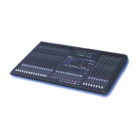
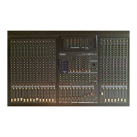
Introduction to the Yamaha GA32/12 or GA24/12 mixing console and manual.
Highlights input/output channels, EQ, faders, GA Diversity, matrixes, and rugged design.
Details the 28 (or 20) monaural input channels and their specifications.
Attenuates input signals by 26 dB.
Adjusts input sensitivity with a specific range.
Reverses the phase of input signals.
Cuts frequencies below 80 Hz with a 12 dB/oct slope.
Lights up when EQ signal level is 3 dB below clipping.
Details the 4-band equalizer and its on/off switch.
Routes post-fader signals from input channels to MIX buses 1-4.
Enable or disable signal routing from input channels to MIX buses 1-4.
Routes input channel signals to MIX buses 5-10.
Selects pre- or post-fader for signals sent to MIX buses 5-10.
Sets the stereo image of signals sent to the ST (stereo) buses.
Sends input channel signals to the ST buses.
Turns the corresponding input channel module on or off.
Routes pre-fader signals to the PFL bus for monitoring.
Adjusts the output level of input channel signals.
Details the two stereo input channel modules and their connections.
Adjusts input sensitivity for stereo channels.
Indicates signal level 3 dB below clipping for EQ output.
Cuts frequencies below 80 Hz for stereo channels.
Details the 4-band EQ and its on/off switch for stereo channels.
Routes stereo input signals to MIX buses 1-4.
Enable or disable stereo signal routing to MIX buses 1-4.
Routes stereo input signals to MIX buses 5-10.
Selects pre/post-fader for stereo signals to MIX buses 5-10.
Adjusts the left/right balance of signals sent to the ST bus.
Sends stereo input channel signals to the ST bus.
Turns the stereo input channel module on or off.
Routes pre-fader stereo signals to the PFL bus for monitoring.
Adjusts the output level of stereo input channel signals.
Configures MIX buses 1-4 as group or AUX buses.
Selects FIX (group) or VARIABLE (AUX) mode for MIX buses 1-4.
Handles MIX bus 1-10 output channels and routing to other buses.
Provides a 3-band equalizer for MIX bus signals.
Adjusts stereo position for MIX buses 1-4 to the ST bus.
Routes MIX bus 1-4 signals to the ST bus.
Routes post-fader MIX bus signals to the AFL bus for monitoring.
Adjusts the output levels of the MIX buses.
Function as group or AUX bus outputs based on Variable/Fix settings.
Function as AUX bus outputs for MIX bus 5-10 signals.
Details the 3-band equalizer for MIX bus signals.
Turns MIX bus equalization on or off.
Adjusts stereo position of MIX bus 1-4 signals to ST bus.
Routes MIX bus 1-4 signals to the ST bus.
Routes post-fader MIX bus signals to AFL bus for monitoring.
Adjusts MIX bus output levels.
Illustrates signal flow in the Variable/Fix select section and Mix section.
Toggles between pre- and post-fader for ST2 OUT jacks.
Mixes ST bus signals to monaural for ST2 OUT jacks.
Adjusts the output level for ST2 OUT jacks.
Routes ST bus post-fader signals to AFL bus for monitoring.
Adjusts the final output level of ST bus signals.
Routes AUX RETURN 1-2 signals to MIX buses 1-4.
Routes AUX RETURN 3-4 signals to MIX buses 5-10.
Adjusts the level of AUX RETURN signals to the ST bus.
Turns the corresponding AUX return on or off.
Routes AUX return signals to the PFL bus for monitoring.
Adjusts the input level of MIX bus 1-4 post-fader signals.
Adjusts ST bus signal levels for L and R channels independently.
Adjusts the output level of Matrix 1-2 signals.
Turns Matrixes 1-2 on or off.
Sends matrix 1-2 post-fader signals to the AFL bus for monitoring.
Selects signal source for monitoring (PFL/AFL or TAPE IN).
Indicates when a PFL bus signal is being monitored.
Adjusts the signal level for C-R MONITOR OUT jacks.
Turns monitoring signals for C-R MONITOR OUT jacks on/off.
Adjusts the signal level for the PHONES jack.
Connects monitoring stereo headphones.
Determines the level of TAPE IN signals sent to the ST buses.
Turns TAPE IN signals to the ST bus on or off.
XLR input jack for connecting a talkback microphone.
Routes talkback signals to MIX buses 1-4.
Routes talkback signals to MIX buses 5-10.
Routes talkback signals to the ST bus.
Adjusts the talkback signal level.
Turns talkback signals on or off.
Selects the signal source to be displayed on the MATRIX meter.
Peak level meter for MIX, ST, Matrix, PFL, AFL, and TAPE IN signals.
Indicate the output level of MIX OUT 1-10.
Indicate the output level of ST1 OUT.
Indicate levels based on METER SELECT switch setting.
Lights up when the console is powered on.
Lights up when phantom power is active.
Balanced XLR-3-31 monaural inputs for channels 1-12, 17-32.
Balanced TRS phone monaural inputs for channels 1-12, 17-32.
TRS phone jacks for external processor insertion into monaural channels.
Controls +48V phantom power for groups of four input channels.
Unbalanced phone jacks for stereo input channels.
Balanced XLR-3-32 jacks outputting MIX bus 1-10 signals.
TRS phone jacks for external processor insertion into MIX buses 1-4.
Unbalanced phone jacks for stereo or monaural AUX returns.
Balanced XLR-3-32 jacks outputting ST bus signals.
Unbalanced phone jacks outputting ST bus signals.
Unbalanced phone jacks outputting Matrix 1/2 signals.
TRS phone jacks for external processor insertion into the ST bus.
Phone jacks for monitoring signals from PFL, AFL, and TAPE IN.
Unbalanced phono jacks for line-level input.
Phono jacks outputting line-level, pre-fader signals.
Allows MIX OUT jacks to function as group or AUX outputs.
Guide to configuring MIX OUT 1-4 as FIX or VARIABLE.
Lists frequency response, THD, hum/noise, voltage gain, crosstalk, EQ, and meters.
Covers power requirements, consumption, dimensions, and weight.
Details input levels, impedance, sensitivity, and connector types.
Details output levels, impedance, and connector types.
Graphical representation of console dimensions in millimeters.
Visual representation of the console's signal path and internal connections.
| Channels | 24 |
|---|---|
| Inputs - Mic Preamps | 24 |
| Inputs - Line | 24 |
| Inputs | 24 |
| EQ | Yes |
| Aux Sends | 6 |
| Phantom Power | Yes |
| Type | Analog |
| Subgroups/Buses | 4 |
| Outputs - Main | 2 |
| Outputs - Other | 4 |
| EQ Bands | 3 |
| Insert Points | Yes |