Do you have a question about the Yamaha MG16/6FX and is the answer not in the manual?
Adherence to safety procedures is crucial for preventing injury and product damage.
Notice regarding lead in solder and other chemicals in components.
Guidance on wiring colors for UK mains plug and cord connection.
Specifies frequency response range and THD+N for ST OUT.
Details residual output noise and equivalent input noise levels.
Lists voltage gain for various input/output combinations.
Details monaural/stereo input gain control and high-pass filter.
Specifies crosstalk levels and monaural/stereo EQ variations.
Details graphic equalizer bands and digital effect programs.
Describes peak LED indicators and stereo level meters.
Notes phantom power supply and included accessories.
Specifies power supply voltage, unit dimensions, and weight.
Details gain, impedance, sensitivity, and connectors for MIC/LINE inputs.
Details rated level, clipping, and connectors for ST, GROUP, AUX outputs.
Provides top and side view diagrams with overall dimensions.
Shows front view and depth dimensions of the unit.
Details the layout and function of channel control knobs and switches.
Details the layout and function of master control knobs and switches.
Diagrams the rear panel input and output connectors.
Details pin assignments for MIC and ST OUT connectors.
Specifies pin assignments for LINE, GROUP, AUX, EFFECT connectors.
Details pin assignments for INSERT I/O, PHONES, and RETURN connectors.
Diagrams showing component placement on main circuit boards.
Illustrates the wiring for the power switch and AC connector.
Details wiring connections between MAIN and JACK circuit boards.
Shows the wiring connections to the PS (Power Supply) circuit board.
Procedure for removing rack mount angles and bottom cover.
Steps to remove the PS circuit board and heat sink.
Instructions for removing the left and right side covers.
Steps for removing the power switch and AC connector.
Procedure for removing the DSP circuit board.
Steps to remove MAIN and JACK circuit boards.
Details the pin assignments and functions of the ZFX-2 CPU.
Pin descriptions for the MCU (Microcontroller Unit).
Pin assignments for the PCM3001E/2K ADA (Analog-to-Digital).
Block diagrams for Hex Inverter and Dual Operational Amplifiers.
Block diagrams for LED Driver and Quad Operational Amplifiers.
Block diagrams for Dual Operational Amplifiers.
Schematic diagram showing component layout for the DSP board.
Schematic diagram showing component layout for the MAIN board.
Schematic diagram showing component layout for the JACK 1/2 board.
Schematic diagram showing component layout for the JACK 2/2 board.
Schematic diagram showing component layout for the PS board.
Specifies environmental factors and default control settings.
Details settings for input, stereo, and EQ controls.
Configuration for digital effects, master send/return, and EQ.
Checks indicator lights and gain level accuracy.
Verifies channel EQ/GEQ performance and crosstalk levels.
Covers LED indicators, distortion, output levels, and noise measurements.
Tests phantom power output and digital effect performance.
Provides an overview of the entire product assembly.
Detailed list of all electrical components with part numbers.
Detailed listing of resistors and capacitors by reference number.
Listings for transistors, LEDs, and push switches.
Details variable resistors, slide potentiometers, and other components.
High-level block diagram showing signal flow.
Detailed circuit schematics for the MAIN board.
Circuit schematics for JACK 1/2 and JACK 2/2 boards.
Circuit schematics for DSP and PS boards.
| Type | Analog Mixer |
|---|---|
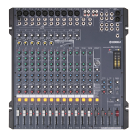
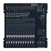
| Number of Channels | 16 |
| Phantom Power | Yes |
| Phantom Power Detail | +48V |
| Faders | 60 mm |
| Line Inputs | 16 |
| Other Inputs | 2 (Stereo) |
| EQ Bands | 3-band EQ |
| Aux Sends | 2 |
| Effects | Yes |
| Effects Processor | SPX Digital Effects (24-bit) |