10
Function and operation of components
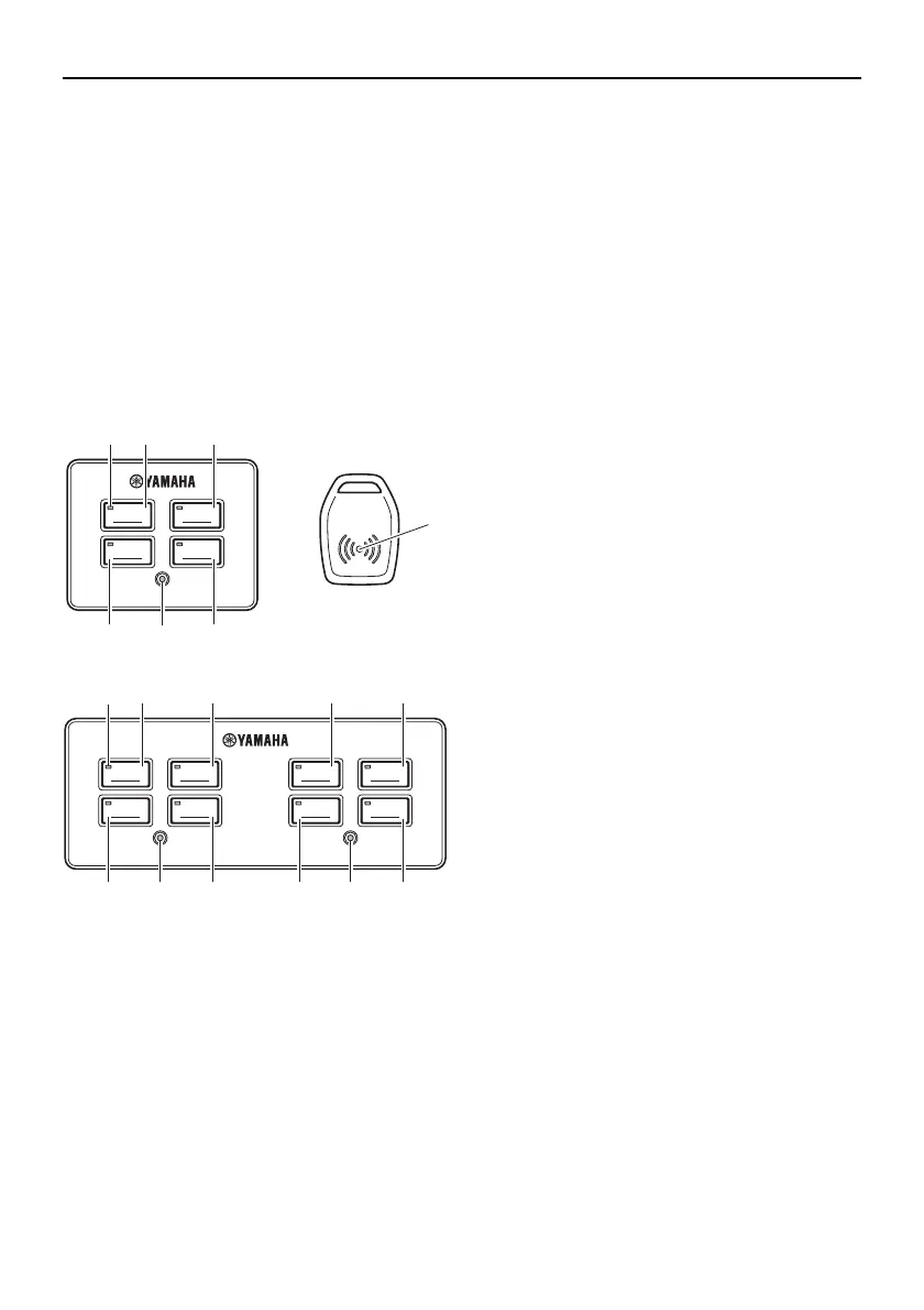
EKS
The EKS consists of the EKS panel and the
EKS fob. EKS functions: EKS locking/un-
locking using EKS fob, ignition ON/OFF and
engine starting and stopping.
The EKS panel for triple engine installations
is equipped with an All ignition switch and an
All start/stop switch. Pressing the All ignition
switch will provide power for all engines.
Pressing the All start/stop switch will start or
stop all engines.
1. EKS fob (2 pcs)
2. Active indicator
3. Ignition switch (PORT)
4. Ignition switch (STBD)
5. Start/stop switch (PORT)
6. Start/stop switch (STBD)
7. Lock indicator
8. Ignition switch (Center)
9. Start/stop switch (Center)
10. All ignition switch
11. All start/stop switch
A. Twin engine application
B. Triple engine application
■ EKS fob
Place and hold the EKS fob over the lock in-
dicator in EKS panel to lock and unlock the
EKS.
• Be sure to lock the EKS when leaving the
boat, or when leaving the operator’s seat if
children are nearby. Also, check that the
lock indicator is blinking.
• Repeated operation of the EKS fob lock/
unlock function may result in improper
operation. Be sure to operate the EKS fob
in at least 1-second intervals.
• When locking/unlocking with the EKS fob,
do not place the key close to devices pos-
sessing a magnetic field, as this may pre-
vent the lock/unlock operation.
• The EKS will allow to register up to four
EKS fobs. Have a Yamaha dealer register
any additional EKS fobs.
• When operating or stopping the boat, be
sure to carry the EKS fob with you and
take care not to lose it.
• If any EKS fob is lost, be sure to have a
Yamaha dealer delete the registration of
the lost key number for security reasons.
• While operating the ignition switch or
engine start switch, do not turn the steer-
ing wheel or perform any system opera-
tions at the same time, otherwise
unexpected errors may occur.
IGNITION IGNITION
START
STOP
START
STOP
A
1
7
432
6
5
IGNITION IGNITION
START
STOP
START
STOP
IGNITION IGNITION
CENTER STBDALL PORT
START
STOP
START
STOP
B
3
10 8
5
4
6
2
11 9 77
0KAW_dtp_data_US.book Page 10 Monday, December 17, 2012 3:35 PM