Do you have a question about the Yamaha K-1020 and is the answer not in the manual?
Component replacement guidelines for specialized parts and adherence to original specifications.
Procedure for verifying insulation and measuring leakage current after service completion.
Visual guides for rear panel connections and ports across different regional models.
Diagram illustrating the audio signal path and interconnections between system components.
Detailed technical specifications of the cassette deck's performance characteristics.
Labeled diagram identifying major internal parts and their reference numbers.
Step-by-step guide for disassembling the mechanism and replacing heads.
Pinout and wiring details for various internal connectors across different models.
Essential pre-adjustment steps including head cleaning and list of necessary tools.
Detailed procedures and target values for performing mechanical calibrations.
Steps for adjusting playback level, EQ, and frequency response.
Steps for setting recording levels, bias, and frequency response.
Layouts for the main and operation circuit boards showing component placement.
Layouts for the power supply and Dolby circuit boards.
Comprehensive diagram showing interconnections between major units and boards.
Details on integrated circuit pinouts, functions, and equivalent part numbers.
Detailed circuit diagrams for audio amplification and signal processing stages.
Circuit diagrams for Dolby, dbx, and control logic functions.
Overall assembly diagram showing major external parts and their numbering.
Detailed assembly diagram of the tape transport mechanism and its components.
Comprehensive list of electrical parts with part numbers and descriptions.
Detailed list of mechanical parts for the tape transport mechanism.
| Brand | Yamaha |
|---|---|
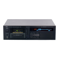
| Model | K-1020 |
| Category | Cassette Player |
| Language | English |