EasyManua.ls Logo

Yamaha KX-670 Service Manual

Yamaha KX-670
31 pages
To Next Page IconTo Next Page
Page #1 background imageLoading...
Page #1 background image

Other manuals for Yamaha KX-670

Question and Answer IconNeed help?

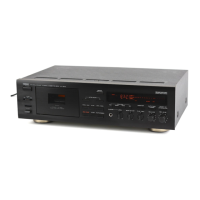
Do you have a question about the Yamaha KX-670 and is the answer not in the manual?
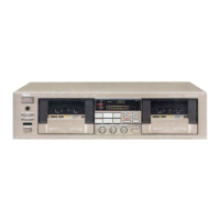
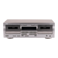
Yamaha KX-670 Specifications

General IconGeneral
TypeCassette Deck
Track System4-track, 2-channel stereo
Tape Speed4.76 cm/s
Total Harmonic Distortion0.8%
MotorDC servo motor
Tape TypeMetal
Noise ReductionDolby B
Frequency Response20 Hz to 20 kHz
InputsLine in
OutputsLine out, Headphones
Output0.5V (Line Out)

Summary

Guidance for Service Personnel

Critical Component and Leakage Current Measurement

Information on critical components and electrical leakage current measurement procedures.

Technical Specifications

General Specifications

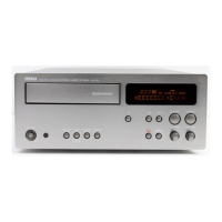
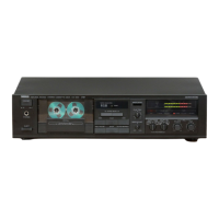
Lists technical specifications including type, heads, motors, frequency response, and power.

System Block Diagram

Disassembly Procedures: Top Cover, Front Panel, and Mechanism

Disassembly Procedures: Motors and Reel Motor

Adjustment Procedures: Preparation and Mechanical Calibration

Adjustment Prerequisites and Required Instruments

List of required instruments, test tapes, and prerequisites for adjustments.

Mechanical Adjustment Steps and Table

Detailed steps and a summary table for mechanical adjustments.

Adjustment Procedures: Tape Speed, Wow/Flutter, and Azimuth

Tape Speed and Wow/Flutter Adjustment

Procedures for adjusting tape speed and wow/flutter using specific instruments.

Electrical Adjustment: Playback Section Calibration

Playback Level Adjustment

Steps to adjust playback level at 315Hz and 10kHz using ACVM.

Playback Frequency Response Check

Procedure to confirm playback frequency response against the 315Hz level.

Electrical Adjustment: Recording Section Calibration

Recording Level and Bias Adjustment

Setting recording level and bias for different tape types (CrO2, Metal).

Total Frequency Response and Test Mode Operation

Adjusting recording bias and verifying frequency response, including test mode.

Printed Circuit Board Layout - Main PCB Foil Side

Printed Circuit Board Layout - Sub PCBs Foil Side

Microcomputer (µ-COM) Data and Pinout

M37420M4-419SP Microcontroller Pin Details

Detailed pin configuration and functions for the M37420M4-419SP µ-COM IC.

Microcomputer Operation Modes and DOLBY NR Control

Integrated Circuit Block Diagrams - Op-Amps and Dolby ICs

Block Diagrams for Op-Amps and Dolby HX PRO

Internal block diagrams for dual op-amp ICs and the Dolby HX PRO processor.

Block Diagram for Dolby Noise Reduction IC

Internal block diagram for the Dolby B & C-Type Noise Reduction Processor IC.

Integrated Circuit Block Diagrams - Additional ICs

Parts List for Carbon Resistors

Related product manuals