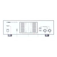
FRONT
PANEL
AND
CONTROLS
“OOOO
ሪርንርንርንርንርንርንርንርንርጋርንርንርጋርን
B90998999990999999929909900909309980099289099209289899080090009989819BG00000909309929009009
ОВО
ООООООСО0000000ФОСОООСОО000ООООО00О000000000000000000с000600000000000000000
Б0б000000ФООООО0О00О0000000000
5
5оббодово
QODGORODODODOODO
GOD
OBGOOOQGOOOOOOODOOOOOOOQQO
688860085500000009
ООООООС000000000С0ФОООО00000000000
ርኃርኃርኃሂጋርጋርጋ
3SbooooooooQo0coOoOOCOODOOCOODOCOODOO0O0000O000000000000000
QOC
2200000000000;
офоодовоовосољловооовоолод
бовосоооосооооооо
00005000000600000000096096000000000606906005
4
ЕС
í
ббобобововобовбобобо
ር;
оборобобобробовобо0000
ОДООООООООООСО000С00000000000000000000000С00Х
OO
с
C
386909080р900050900006009060090000906009000000000060090609900
О
0009920099
BOIS
оососоооососвовосоооосоооосоо0овоооововосоовоовозо0о
2
883893B06999000800999906
OOQOOOOCOOOO0O0O0O0QOOOQOOOOO
обб0800000000080009080680
5566
2
ооо
ЈООООООООООЕ
О,
OOOOOQOQOOOOOCOOOQGO
ООООООО000000000000
ርጋርጋርጋርጋርጋኃርጋርጋርንርኃርጋኃርጋርጋኒጋርጋርኃርጋ
5
і
3B53569990999980999990999999390090899
ссобазвовобововобозабобо0б0900900000
ОВО
ЗОО
ОУ
GO
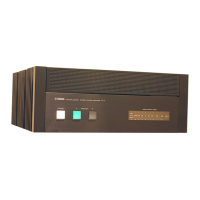
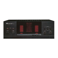
YAMAHA
NATURAL
SOUND
STEREO
POWER|
AMPLIFIER
M~4
SPEAKERS
-40
-30 ~20
-10
-5
и
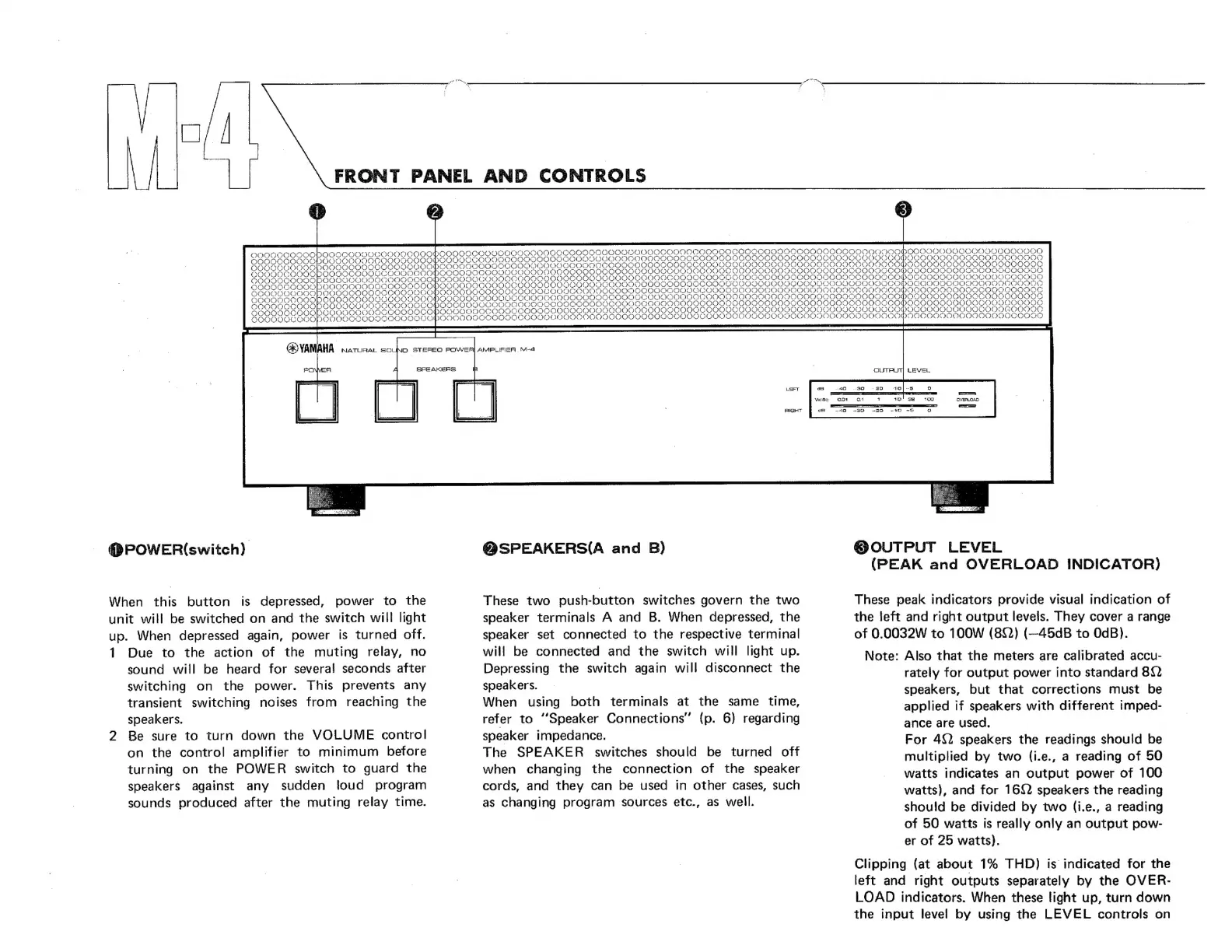
@POWER(switch)
When
this
button
is
depressed,
power
to
the
unit
will
be
switched
on
and
the
switch
will
light
up.
When
depressed
again,
power
is
turned
off.
1
Due
to
the
action
of
the
muting
relay,
no
sound
will
be
heard
for
several
seconds
after
switching
on
the
power.
This
prevents
any
transient
switching
noises
from
reaching
the
speakers.
2
Be
sure
to
turn
down
the
VOLUME
control
on
the
control
amplifier
to
minimum
before
turning
on
the
POWER
switch
to
guard
the
speakers
against
any
sudden
loud
program
sounds
produced
after
the
muting
relay
time.
QSPEAKERS(A
and
B)
These
two
push-button
switches
govern
the
two
speaker
terminals
A
and
B.
When
depressed,
the
speaker
set
connected
to
the
respective
terminal
will
be
connected
and
the
switch
will
light
up.
Depressing
the
switch
again
will
disconnect
the
speakers.
When
using
both
terminals
at
the
same
time,
refer
to
"Speaker
Connections"
(p.
6)
regarding
speaker
impedance.
The
SPEAKER
switches
should
be
turned
off
when
changing
the
connection
of
the
speaker
cords,
and
they
can
be
used
in
other
cases,
such
as
changing
program
sources
etc.,
as
well.
@
OUTPUT
LEVEL
(PEAK
and
OVERLOAD
INDICATOR)
These
peak
indicators
provide
visual
indication
of
the
left
and
right
output
levels.
They
cover
a
range
of
0.0032W
to
100W
(80)
(—45dB
to
OdB).
Note:
Also
that
the
meters
are
calibrated
accu-
rately
for
output
power
into
standard
80)
speakers,
but
that
corrections
must
be
applied
if
speakers
with
different
imped-
ance
are
used.
For
452
speakers
the
readings
should
be
multiplied
by
two
(i.e.,
a
reading
of
50
watts
indicates
an
output
power
of
100
watts),
and
for
1692
speakers
the
reading
should
be
divided
by
two
(i.e.,
a
reading
of
50
watts
is
really
only
an
output
pow-
er
of
25
watts).
Clipping
(at
about
1%
THD)
is
indicated
for
the
left
and
right
outputs
separately
by
the
OVER-
LOAD
indicators.
When
these
light
up,
turn
down
the
input
level
by
using
the
LEVEL
controls
on
 Loading...