Do you have a question about the Yamaha M2500 and is the answer not in the manual?
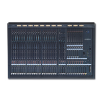
Details controls for monaural input channels, including GAIN, EQ, and routing.
Explains controls for stereo input channels, including GAIN, EQ, and routing options.
Covers output controls for AUX buses 1-6, including faders and AFL.
Describes controls for output channels A7-A14/G1-G8, related to AUX/GROUP buses.
Details controls for output channels G1-G8/A7-A14, related to GROUP/AUX buses.
Explains the switch that exchanges GROUP and AUX bus destinations.
Controls for ST OUT L/R and MONO/C OUT signals, including MATRIX assignment.
Describes the eight-channel matrix mixer controls for flexible signal routing.
Controls for selecting and monitoring signals via MONITOR OUT and PHONES jacks.
Controls for talkback microphone input and internal test tone oscillator.
Allows selection of signal sources for the meter bridge display.
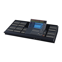
Features for scene memory storage, recall, and utility settings.
Explanation of scene memory, its capacity, and factory settings.
Overview of Normal, Check, and Utility modes for scene memory operations.
Procedures for recalling and storing scenes in Normal mode.
How to check or edit scene settings without affecting current output.
Steps for accessing and configuring Utility mode settings, including MIDI and memory.
Using scene memory numbers 1-8 as mute group switches.
Describes fallback operation if scene memory fails.
Messages related to MIDI data reception errors and buffer issues.
Covers errors like memory full, protect errors, and general system malfunctions.
Explains messages for low battery, no data stored, and abnormal voltage.
Overall performance specs like THD, frequency response, and input/output levels.
Detailed table of input/output levels, impedance, and connector types.
Connector wiring details and included items.
Specifies MIDI channel usage and program change to scene memory mapping.
Explains control change assignments and the echo back function.
Details format for scene memory bulk data transmission and requests.
| Brand | Yamaha |
|---|---|
| Model | M2500 |
| Category | Music Mixer |
| Language | English |