EasyManua.ls Logo

Yamaha MSR800W Service Manual

Yamaha MSR800W
36 pages
To Next Page IconTo Next Page
Page #1 background imageLoading...
Page #1 background image
SERVICE MANUAL
CONTENTS(目次)
SPECIFICATIONS(総合仕様)............................................................3
PERFORMANCE GRAPH
(特性図)...................................................4
PANEL LAYOUT
(パネルレイアウト)..................................................4
CIRCUIT BOARD LAYOUT
(ユニットレイアウト)..............................5
DIMENSIONS
(寸法図)......................................................................5
WIRING DIAGRAM
(結線図)..............................................................6
IC BLOCK DIAGRAM
(ICブロック図)................................................8
DISASSEMBLY PROCEDURES
(分解手順)......................................9
CIRCUIT BOARDS
(シート基板図)...................................................12
INSPECTIONS
(検査)......................................................................15
PARTS LIST
BLOCK DIAGRAM
(ブロックダイアグラム)
OVERALL CIRCUIT DIAGRAM(回路図)
POWERED SUBWOOFER
MSR800W
PA
011778
200505-115500
HAMAMATSU, JAPAN
Copyright (c) Yamaha Corporation. All rights reserved. PDF-K126 ’05.06
のサー ルは パル
(ECF 無塩素系漂白パル 使用 す。
This document is printed on chlorine free (ECF) paper.
w
w
w
.
x
i
a
o
y
u
1
6
3
.
c
o
m
Q
Q
3
7
6
3
1
5
1
5
0
9
9
2
8
9
4
2
9
8
T
E
L
1
3
9
4
2
2
9
6
5
1
3
9
9
2
8
9
4
2
9
8
0
5
1
5
1
3
6
7
3
Q
Q
TEL 13942296513 QQ 376315150 892498299
http://www.xiaoyu163.com

Other manuals for Yamaha MSR800W

Question and Answer IconNeed help?

Do you have a question about the Yamaha MSR800W and is the answer not in the manual?

Yamaha MSR800W Specifications

General IconGeneral
BrandYamaha
ModelMSR800W
CategorySubwoofer
LanguageEnglish

Summary

Important Notices and Warnings

General Safety and Handling Precautions

Essential service, safety, and chemical content notices for product handling and maintenance.

United Kingdom Wiring Information

Specific instructions for connecting the mains lead in the UK, detailing wire color to terminal mapping.

Product Specifications

General Specifications

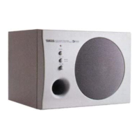
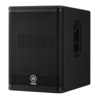
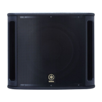
Lists overall product type, speaker, frequency range, output level, dimensions, weight, and accessories.

Amplifier Unit Specifications

Details maximum output power, input sensitivity, controls, connectors, and indicators for the amp unit.

Panel Layout and Performance Graph

Performance Graph

Displays frequency response characteristics of the subwoofer at various cutoff frequencies.

Rear Panel Layout

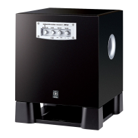
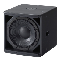
Identifies and labels controls and connectors on the rear panel of the subwoofer.

Physical and Circuit Board Layouts

Circuit Board Layout

Illustrates the internal placement of key circuit boards like AMP, MIX, INPUT, and SW.

Unit Dimensions

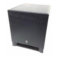
Provides detailed measurements (width, height, depth, diameter) of the subwoofer unit.

Wiring Diagrams

Wiring Diagram (Versions U, H, B, A, O)

Shows the internal wiring connections for specific model versions of the subwoofer.

Wiring Diagram Version J

Wiring Diagram (Version J)

Details specific wiring connections applicable to the 'J' model version.

Integrated Circuit Block Diagrams

IC Block Diagrams

Illustrates the functional block diagrams for integrated circuits like TL072CP, NJM2068L-D, and NJM4580L.

Disassembly Procedures: Woofer and Amplifier

Woofer Disassembly

Step-by-step guide for removing the woofer, including screw identification and connector disconnection.

Amplifier Assembly Disassembly

Instructions for removing the amplifier assembly, detailing screw counts and visual references.

Disassembly Procedures: Components

Power Transformer Removal

Guide to safely remove the power transformer, referencing associated bolts and diagrams.

Circuit Board Removal

Steps for removing the AMP, INPUT, and other circuit boards, noting screw counts and connector disconnections.

Disassembly Procedures: Circuit Boards

MIX, SW, AC INLET, HARM Circuit Board Removal

Procedures for removing MIX, SW, AC INLET, and HARM circuit boards, including screw and connector details.

Circuit Board Diagrams

AMP and INPUT Circuit Boards

Detailed schematic diagrams of the AMP and INPUT circuit boards, showing component layouts.

Circuit Board Diagrams (Continued)

INPUT Circuit Board Details

Further detailed layout and component placement for the INPUT circuit board.

Circuit Board Diagrams (Continued)

MIX, SW, AC INLET, HARM Circuit Boards

Schematic diagrams illustrating the component layout for MIX, SW, AC INLET, and HARM circuit boards.

Inspections and Measurements

Measurement Conditions

Specifies the required voltage, resistance, control settings, and temperature for accurate product testing.

Power On and Idling Current Inspections

Details checks for power-on muting time, POWER indicator, and idling current adjustment procedures.

Inspections and Measurements (Continued)

Peak/Limit Indicator, Phase Switch, and Protection Circuit Tests

Procedures for testing the PEAK/LIMIT indicator, PHASE switch functionality, and protection circuit response.

Parts List Information

Destination Abbreviations

A key defining abbreviations used for different country or regional model destinations.

Parts List Warnings and Notes

Important notes regarding special parts, availability, and part number conventions in the parts list.

Overall Assembly Diagram

Exploded View of Overall Assembly

An illustrated exploded view showing the assembly of the subwoofer unit with numbered components.

Amplifier Assembly Details

Amplifier Assembly Diagram

A detailed diagram showing the arrangement of parts within the amplifier assembly, labeled with letters.

Electrical Parts List

Electrical Components List

A comprehensive list of electrical components including circuit boards, capacitors, transistors, and connectors with part numbers.

Electrical Parts List (Continued)

Electrical Components List (Continued)

Continues the list of electrical components, detailing resistors, capacitors, and other parts with specifications.

Electrical Parts List (Continued)

Electrical Components List (Continued)

Further lists electrical components such as transistors, diodes, ICs, and connectors with their respective part numbers.

Electrical Parts List (Continued)

Electrical Components List (Continued)

Continues listing electrical components including capacitors, diodes, and connectors with specifications.

Electrical Parts List (Continued)

Electrical Components List (Continued)

Lists electrical components like diodes, transistors, and fuses, providing part numbers and remarks.

Electrical Parts List (Continued)

Electrical Components List (Continued)

Lists electrical components, primarily resistors and flame-proof resistors, with detailed specifications.

Electrical Parts List (Continued)

Electrical Components List (Continued)

Lists various electrical components such as resistors, relays, potentiometers, and circuit boards.

Electrical Parts List (Continued)

Power Transformers and AC Cords

Lists specific power transformer part numbers for different destinations and AC cord options.

System Block Diagram

System Block Diagram Overview

A high-level block diagram showing the interconnections of major functional units like INPUT, MIX, AMP, SW, HARM, AC INLET.

Overall Circuit Diagrams

Amplifier (AMP) Circuit Diagram

Detailed schematic diagram for the amplifier section, including component part numbers and designations.

Overall Circuit Diagrams (Continued)

Mixer (MIX) Circuit Diagram

Detailed schematic diagram for the mixer section, showing operational amplifiers and control signal paths.

Overall Circuit Diagrams (Continued)

Input (INPUT) Circuit Diagram

Detailed schematic diagram for the input section, illustrating signal processing and connector interfaces.

Overall Circuit Diagrams (Continued)

AC Inlet, SW, and Harm Circuit Diagrams

Schematic diagrams for AC inlet, switch, and harm circuits, including power supply and protection elements.

Related product manuals