Do you have a question about the Yamaha PortaTone PSR-740 and is the answer not in the manual?
| Display | LCD |
|---|---|
| Speakers | 12cm x 2 + 3cm x 2 |
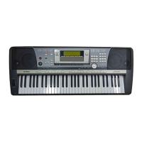
| Keyboard | 61 keys with Touch Response |
| MIDI | In/Out |
| Effects | Reverb, Chorus, DSP |
| Sequencer | 16-track, 5 songs |
| Connectivity | MIDI In/Out |
| Polyphony | 64-note |
Identification and function of controls on the top panel.
Identification and function of controls on the rear panel.
High-level overview of the PSR-740 internal electronic system.
High-level overview of the PSR-640 internal electronic system.
Steps to remove the lower case and DM circuit board.
Procedures for removing INV, MIC, and MIC-JACK boards.
Steps to remove PN(WH1), PN(WH2), PN(WH3) circuit boards.
Procedures for removing LCD, AM(HP), JACK, and Woofer speakers.
Instructions for reassembling the keyboard components.
Pin assignments and functions for the main CPU ICs.
Pin assignments for the tone generator and VOP3 ICs.
Pin assignments for the SWP30B wave processor IC.
Pin assignments for CPU, ADC, and DAC ICs.
Pin assignments for FDC and LCD controller ICs.
Block diagrams for inverter, AND/OR, DEMUX, and interface ICs.
Component layout and identification for the PSR-740 DM circuit board.
Component layout and identification for the PSR-640 DM circuit board.
Component layouts for PN(PN1) through PN(PN4) and PN(ENC) boards.
Component layouts for JACK, MK, INV, MIC, and MKS3 circuit boards.
Component layouts for AM(AM), AM(HP), AM(PSW), AM(VR) circuit boards.
Instructions for preparing and entering the diagnostic test modes.
How to run tests and move between them.
Detailed list of tests and their acceptance criteria.
Steps to reset all data to factory default settings.
Structure of MIDI messages for transmission and reception.
Details on MIDI message compatibility for PSR-740.
Details on MIDI message compatibility for PSR-640.