EasyManua.ls Logo

Yamaha RX-V2090 User Manual

Yamaha RX-V2090
40 pages
To Next Page IconTo Next Page
Page #1 background imageLoading...
Page #1 background image
OWNER’S MANUAL
Contents
PROFILE OF THIS UNIT ............................ 6
SPEAKER SETUP FOR THIS UNIT........... 7
CONNECTIONS ......................................... 9
ADJUSTMENT BEFORE OPERATION.... 16
BASIC OPERATIONS .............................. 19
TUNING OPERATIONS ........................... 22
USING THE DIGITAL SOUND FIELD
PROCESSOR (DSP) ................................ 26
SETTING THE SLEEP TIMER ................. 31
REMOTE CONTROL TRANSMITTER ..... 32
CAUTION: TO REDUCE THE RISK OF
ELECTRIC SHOCK, DO NOT REMOVE
COVER (OR BACK). NO USER-SERVICEABLE
PARTS INSIDE. REFER SERVICING TO
QUALIFIED SERVICE PERSONNEL.
CAUTION
RISK OF ELECTRIC SHOCK
DO NOT OPEN
Explanation of Graphical Symbols
The lightning flash with arrowhead
symbol, within an equilateral triangle,
is intended to alert you to the
presence of uninsulated “dangerous
voltage” within the product’s
enclosure that may be of sufficient
magnitude to constitute a risk of
electric shock to persons.
The exclamation point within an
equilateral triangle is intended to
alert you to the presence of
important operating and
maintenance (servicing) instructions
in the literature accompanying the
appliance.
IMPORTANT!
Please record the serial number of this
unit in the space below.
Model:
Serial No.:
The serial number is located on the rear
of the unit.
Retain this Owner’s Manual in a safe
place for future reference.
WARNING
TO REDUCE THE RISK OF FIRE OR
ELECTRIC SHOCK, DO NOT EXPOSE
THIS UNIT TO RAIN OR MOISTURE.
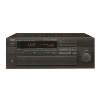
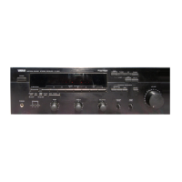
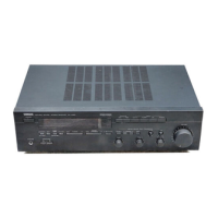
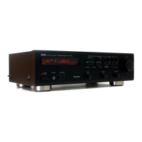
RX-V2090
Natural Sound Stereo Receiver

Questions and Answers:

Yamaha RX-V2090 Specifications

General IconGeneral
TypeStereo Receiver
Channels2
Power Output100 W per channel
Frequency Response20Hz to 20kHz
Input Sensitivity150mV (line)
Input Impedance47kΩ (line)
Signal-to-Noise Ratio100 dB
Channel Separation70 dB
Video ConnectionsComposite Video Inputs

Summary

SAFETY INSTRUCTIONS

PRE-OPERATION CAUTIONS AND FCC INFORMATION

FCC INFORMATION

Important notices regarding product modification, shielded cables, and FCC compliance.

SUPPLIED ACCESSORIES

UNIT FEATURES AND DOOR OPERATION

OPEN/CLOSE THE CONTROL DOOR

Instructions for opening and closing the front control panel door.

PROFILE OF THIS UNIT

Digital Sound Field Processing Overview

Explains the benefits and technology behind Yamaha's Digital Sound Field Processor.

Dolby Pro Logic Surround Decoder

Describes the Dolby Pro Logic Surround Decoder for enhanced movie audio.

SPEAKER SETUP FOR THIS UNIT

SPEAKERS TO BE USED

Details the types of speakers required for optimal sound field quality.

Seven-Speaker Configuration

Recommends a seven-speaker setup for the best sound field performance.

SPEAKER PLACEMENT GUIDELINES

CONNECTIONS OVERVIEW

CONNECTING SPEAKERS

How to Connect Speakers

General guidelines for connecting speaker wires and ensuring proper polarity.

ABOUT THE ACCESSORY TERMINALS

LOW PASS terminal

Terminal for output to a monaural amplifier driving a subwoofer.

AC OUTLETS

Outlets for connecting power cords of other components to the unit.

ACCESSORY TERMINAL DETAILS

MAIN CH MAIN IN terminals

Terminals for line input to the built-in main channel amplifier.

5CH DISCRT INPUT terminals

Terminals for connecting a Dolby Surround AC-3 decoder.

VIDEO CONNECTIONS

CONNECTING S VIDEO TERMINALS

Instructions for connecting S-Video and composite video sources.

ON SCREEN DISPLAY

Information on displaying DSP program names and settings on a video monitor.

ROOM 2 MULTI-ROOM SETUP

CONNECTING TO ROOM 2 EQUIPMENT

Details on connecting optional components for multi-room audio/video.

ANTENNA CONNECTIONS

Connecting the AM loop antenna

Guide for connecting the AM loop antenna for optimal reception.

ADJUSTMENT BEFORE OPERATION

SPEAKER BALANCE ADJUSTMENT

Procedure to balance sound output levels between all speakers for optimal performance.

SPEAKER CONFIGURATION MODES

Seven and Five Speaker Configuration Modes

Explains NORMAL and WIDE center channel modes for specific speaker setups.

SPEAKER LEVEL ADJUSTMENTS

Adjust the BALANCE control

Balancing left and right front speaker output levels for sound consistency.

Adjust the CENTER LEVEL

Adjusting the center speaker's sound output level initially.

FINE-TUNING SPEAKER LEVELS

Adjusting the FRONT LEVEL

Fine-tuning front speaker output levels using the remote.

Adjusting the CENTER LEVEL

Fine-tuning center speaker output levels using the remote.

DELAY TIME ADJUSTMENT

Adjusting the effect of DELAY TIME

Adjusting the time difference for sound effects and ambient noise.

SETTING THE SLEEP TIMER

To set the SLEEP time

Setting the unit to turn off automatically after a specified period.

REMOTE CONTROL TRANSMITTER OPERATIONS

Battery installation

Instructions for installing batteries in the remote control transmitters.

REMOTE CONTROL FUNCTIONS

For Control of This Unit

Overview of remote control buttons for operating the main unit.

OTHER COMPONENT CONTROL

CD player keys

Controls for operating a compact disc player.

Tape deck keys

Controls for operating a tape deck.

REMOTE CONTROL "LEARNING" FUNCTION

YPC-USER-LEARN switch

How to set the switch for preset codes, learned functions, or learning mode.

PROGRAMMING THE REMOTE CONTROL

To learn a new function

Step-by-step guide for programming new functions into the remote.

REMOTE CONTROL MAINTENANCE

Troubleshooting guide

Common issues with the remote and their remedies.

TROUBLESHOOTING

Amplifier Issues

Common problems related to power, sound output, and hum, with solutions.

FM Reception Issues

Troubleshooting noisy FM stereo reception and tuning problems.

SPECIFICATIONS

Audio and Tuner Specifications

Detailed technical specs for audio output, FM/AM tuner, and video sections.

Related product manuals