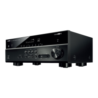
Do you have a question about the Yamaha RX-V483/HTR-4071 and is the answer not in the manual?
| Channels | 5.1 |
|---|---|
| Frequency Response | 10 Hz - 100 kHz |
| Total Harmonic Distortion (THD) | 0.09% |
| HDMI Input | 4 |
| HDMI Output | 1 |
| HDMI Pass-through | Yes |
| Audio Return Channel | Yes |
| Digital Audio Input (Optical) | 1 |
| Digital Audio Input (Coaxial) | 1 |
| Analog Audio Input | 4 |
| Subwoofer Output | 1 |
| Phono Input | Yes |
| Speaker Output | 5 |
| FM/AM Tuner | Yes |
| Wi-Fi | Yes |
| Bluetooth | Yes |
| Front AV Input | 1 |
| USB Input | 1 |
| AirPlay | Yes |
| Power Output (8 ohms) | 80 W |
| Rated Output Power (1kHz, 1ch driven) | 100 W |
| Rated Output Power (20Hz-20kHz, 2ch driven) | 80 W |
| Supported Audio Formats | Dolby Digital, Dolby Digital Plus, Dolby TrueHD, DTS, DTS-HD Master Audio, MP3, WMA, MPEG-4 AAC |
Critical steps when replacing DIGITAL P.C.B. or IC23 to avoid "Internal Error".
Information on components marked with ⚠ requiring exact replacement parts for safety.
Procedure for verifying insulation and measuring AC leakage current on 120V models.
Recommended types of lead-free solder and caution regarding melting points.
Detailed parameters for audio output, frequency response, distortion, and tone controls.
Details on video signal types, levels, and signal-to-noise ratio.
Tuning range and sensitivity for FM and AM tuner sections.
Power supply voltage, power consumption, dimensions, and weight.
Illustration showing the top and front views of internal PCBs and major components.
Critical safety measures, including high voltage warnings and capacitor discharging procedures.
Step-by-step instructions for safely removing the unit's top cover.
Instructions for removing the front panel unit, including screw and connector disconnection.
Procedure for removing the network module, including the use of a special tool.
Steps to remove the DIGITAL P.C.B., including connector and board disconnection.
Procedure for removing the amplifier unit, detailing screw and connector removal.
How to check firmware version and checksum using the self-diagnostic function.
Procedure for initializing the backup IC (EEPROM) after firmware update.
Step-by-step guide for updating the receiver's firmware using an internet connection.
How to confirm the firmware has been successfully updated to the latest version.
Step-by-step guide for updating the receiver's firmware using a USB thumb drive.
Explanation of the self-diagnostic function's main and sub-menus for inspection.
Instructions on how to start, start in protection cancel mode, and cancel the self-diagnostic function.
Explains how protection functions work during self-diagnosis and how to handle them.
Explanations of specific self-diagnostic tests for audio, video, network, and system functions.
Information on display data, grid assignments, and anode connections for the unit.
Detailed pin configurations and functions for key ICs like MN864788A.
Comprehensive list of pin functions for various interfaces like Video, Audio, TMDS, DDC, SPI.
Illustrates wiring connections and signal flow between major circuit boards.
Block diagram detailing the signal paths for video and audio processing.
Block diagram showing the power supply distribution to various system components.
Visual diagram showing component layout on the DIGITAL P.C.B. (Side A).
Visual diagram showing component layout on the DIGITAL P.C.B. (Side B).
Visual diagrams showing component layouts for various OPERATION boards (Side A).
Detailed schematics for the digital processing and interface circuits.
Schematic illustrating the power supply circuitry, including transformers and regulators.
Schematics for main amplifier stages, audio inputs, and selector circuits.
List of electrical components, including abbreviations and part numbers.
Detailed list of digital section components with part numbers, descriptions, and ratings.
List of replacement components for the operation sections.
List of replacement components for the main amplifier sections.
Comprehensive table of carbon resistor values and corresponding part numbers.
List of included accessories and specialized tools for service.
Schematic diagram and physical layout of the remote control unit.
Table mapping key numbers and names to their respective codes and functions.
Solutions for errors encountered during firmware update, including network and USB issues.
Steps to recover from issues like no power after update or error confirmation.
Troubleshooting steps for when the remote control stops working, focusing on Advanced Setup settings.
 Loading...