Do you have a question about the Yamaha Stagepas 600i and is the answer not in the manual?
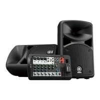
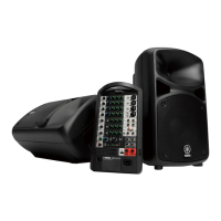
Detailed specifications for the portable PA system, including power output, frequency response, THD, hum & noise, crosstalk, phantom voltage, weight, package contents, and power consumption.
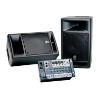
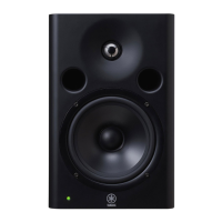
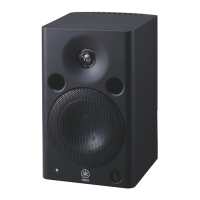
Specifications for the speaker units, including enclosure type, driver details, crossover frequency, frequency range, maximum output level, and coverage angle.
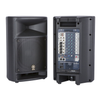
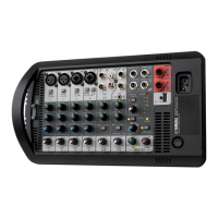
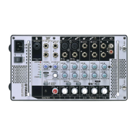
Overview of the mixer panel layout, identifying all controls, switches, connectors, and indicators with descriptions.
Diagram illustrating the physical arrangement of circuit boards within the mixer unit, labeling major components like AMPS, DSP, and various SUB/MIX boards.
Detailed dimensional drawings of the mixer unit, including overall size and mounting details.
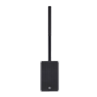
Detailed dimensional drawings of the speaker unit, including overall size, views from different angles, and pole diameter.
Step-by-step instructions for safely disassembling the STAGEPAS 600i unit, covering grille and speaker removal.
Pin description and function for the AK5386VT ADC LSI, detailing input/output and specific functions.
Pin description and function for the MFI341S2162 iPod/iPhone Authentication LSI.
Pin description and function for the WM8524CGEDT/R DAC LSI, detailing I/O and specific functions.
Pin description and function for the LC87F1HC8AF5BT3WA-2H USB Microcontroller LSI.
Pin description and function for the LM3S808-IQN50-C2T Main Microcontroller LSI.
Pin description and function for the PCM1781DBQR DAC LSI, detailing Digital to Analog Conversion.
Pin description and function for the PCM1803ADBR ADC LSI, detailing Analog to Digital Conversion.
Pin description and function for the PCM1803DBR ADC LSI, detailing Analog to Digital Conversion.
Pin description and function for the YLD330-EZE2 LED Driver LSI.
Pin description and function for the YSS952-QZE2A DSP LSI, detailing Digital Signal Processing.
Component layout diagram for the AMPS circuit board, showing placement of parts on the component and pattern sides.
Component layout diagram for the DSP circuit board, showing placement of parts on the component and pattern sides.
Component layout diagram for the MIX61 circuit board, showing placement of parts on the component and pattern sides.
Component layout diagram for the MIX62 circuit board, showing placement of parts on the component and pattern sides.
Component layout diagram for the NET61 circuit board, showing placement of parts on the component side.
Component layout diagram for the NET62 circuit board, showing placement of parts on the component side.
Component layout diagram for the SUB61 circuit board, showing placement of parts on the component and pattern sides.
Component layout diagram for the SUB62 circuit board, showing placement of parts on the component and pattern sides.
Component layout diagram for the SUB63 circuit board, showing placement of parts on the component and pattern sides.
Required items for test preparation, including PC specifications, serial interface jig set, and software.
Instructions for downloading and copying service inspection application files from the YSISS homepage.
Diagram illustrating the physical connection setup for the diagnostic test between PC, mixer, and iPod/iPhone.
Details on measuring instruments, jigs, and filters required for system inspection.
Guidelines for selecting and using measuring instruments and jigs, including input impedance and filters.
Information on specific filters to be used for measuring SPEAKERS OUT (L/R) and other items.
Diagram and instructions for connecting the PC, mixer, DSP, and serial interface jig set for inspection.
List of necessary tools and software for firmware updating, including PC requirements and specific jig sets.
Steps for preparing the update software, including downloading and copying files to the PC's C drive.
Diagram and instructions for connecting the PC, mixer, and diagnostic jig set for the firmware update process.
Flowchart detailing the initial power-on sequence, including device initialization and mode selection.
Explanation of the power-off protection function, its purpose, and operating procedures to prevent click noise.
| Product color | Black |
|---|---|
| Frequency range | 55 - 20000 Hz |
| RMS rated power | 680 W |
| XLR in | Yes |
| USB ports quantity | 1 |
| Connectivity technology | Wired |
| Karaoke | - |
| Equalizer bands quantity | 3 |
| Speaker type | 2-way |
| Number of speakers | 2 |
| Woofer diameter (imperial) | 10 \ |
| AC input voltage | 100-240 V |
| Power source type | AC |
| AC input frequency | 50 - 60 Hz |
| Weight | 25400 g |
|---|---|
| Transmitter weight | 3800 g |