Do you have a question about the Yamaha T-2 and is the answer not in the manual?
Connects the T-type internal antenna to the 300Ω BAL terminals for best reception.
Connects an outdoor FM antenna to 300Ω or 75Ω terminals for improved reception.
Facilitates connection of the T-2 tuner to an outdoor antenna or other via coaxial cable.
Used for setting proper recording level for FM broadcasts by outputting a 333 Hz signal.
Detects FM multipath interference by signal meter quiver, aiding antenna adjustment.
Explains the front end circuit using three dual-gate MOS FETs and an RF MODE switching circuit.
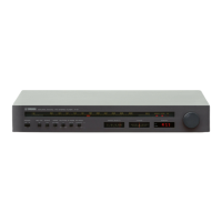
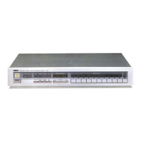
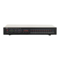
Describes the STATION indicator that digitally displays the tuned frequency.
Details the AUTO DX circuit and its IF band switching for optimal reception.
Explains Yamaha's method for improving selectivity while reducing distortion.
Explains the unique DC-NFB-SWITCHING circuit for stereo demodulation and pilot signal cancellation.
Details the signal meter, de-tuning detector, interference detector, and timing circuit for muting.